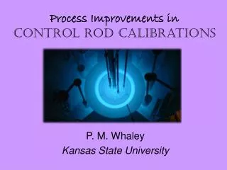
Control Rod Drive System (PRD) Overview
Control Rod Drive System (PRD) Overview. P. J. Sebastiani University of Pittsburgh ME 2120 February 7, 2011. Control Rod Drive System (PRD) Agenda. Purpose of the System Background Required Outputs Initial Conditions Time-Dependent Boundary Conditions Required Geometry Pertinent Physics

Control Rod Drive System (PRD) Overview
E N D
Presentation Transcript
Control Rod Drive System (PRD) Overview P. J. Sebastiani University of Pittsburgh ME 2120 February 7, 2011
Control Rod Drive System (PRD)Agenda • Purpose of the System • Background • Required Outputs • Initial Conditions • Time-Dependent Boundary Conditions • Required Geometry • Pertinent Physics • Viewable Signals
Control Rod Drive System (PRD)Purpose of the System • Reactivity Control • The reactor core utilizes Rod Cluster Control Assemblies which provide reactivity control for: • Rapid shutdown (i.e., reactor trip) • Reactivity changes due to temperature changes with power (i.e., power defect) • Reactivity changes due to coolant temperature changes in the power range (i.e., moderator temperature feedback) • Reactivity changes due to void formation
Control Rod Drive System (PRD)Background • Rod Cluster Control Assemblies (RCCAs) • RCCAs consists of absorber rods attached to a spider connector which, in turn, is connected to a drive shaft. • RCCA control elements consist of cylindrical neutron absorber rods (control rods). • The control rods extend the full length of the core when fully inserted. • The RCCAs are arranged into groups and electrically interconnected so that the entire group moves together. • Reactivity of the core is changed by raising or lowering a group within the core.
Control Rod Drive System (PRD)Background (continued) • RCCA Diagram (within Fuel Assembly)
Control Rod Drive System (PRD)Background (continued) • RCCA Groups in the Core NOTE: AP1000 will have a different rod pattern
Control Rod Drive System (PRD)Background (continued) • Control Rod Drive Mechanism • The RCCAs are positioned by latch-type magnetic jack control rod drive mechanisms (CRDMs) mounted on the reactor vessel head • Used to raise and lower the RCCAs (in/out of core) • Instantly releases RCCAs when necessary for rapid reactor shutdown (i.e., Reactor Trip) • Latch positions are referred to as “steps” • Stepping distance: 5/8 inch (in) • Total rod position indication length: ~230 steps (~144 in) • Maximum Rods Move Speed: 45 inch/min (72 steps/min)
Control Rod Drive System (PRD)Required Outputs • Rods Move Speed • Manual Control (default setting): 48 steps/min • Automatic Control: up to 72 steps/min (see Pertinent Physics Section) • Rods Move Direction • In or Out
Control Rod Drive System (PRD)Initial Conditions • Control Scheme • Automatic or Manual Control • Rod Insertion Limits • Technical Specification Limits on rod position to ensure adequate Shutdown Margin for the core • Rod Position • The current rod position at the start of the simulation
Control Rod Drive System (PRD)Time-Dependent Boundary Conditions • Core Average Temperature (TAVG) • Calculated using cold leg (TCOLD) and hot leg (THOT) temperature values • Input to the “Temperature Error” signal • Reactor Power (2 separate inputs) • One input from Turbine Impulse Pressure (for Temperature Error calculation) • Will this be available in PANTHER model? • One input from Power Range Detector (for Power Mismatch calculation)
Control Rod Drive System (PRD)Time-Dependent Boundary Conditions (cont.) • Trip Breaker Setting • i.e., Manual Reactor Trip • Open or Closed
Control Rod Drive System (PRD)Required Geometry • Control Rod Pattern • See Background Section for example
Control Rod Drive System (PRD)Pertinent Physics • Total Error Calculation
Control Rod Drive System (PRD)Pertinent Physics • Rods Move Speed
Control Rod Drive System (PRD)Viewable Signals • Control Scheme Selection • AUTO or MANUAL • Rod Position (steps withdrawn) • Rod Speed (steps/min) • Total Error • Rods Move Indication • Lamp for moving or not moving • “Clicking” noise during rod movement