Download
1 / 72
740 likes | 851 Vues
Explore proven RFI mitigation methods in radio astronomy, including blanking, cancellation, and the challenges faced in reducing RFI impact on data integrity. Learn about the importance of automated, reliable mitigation machinery to safeguard astronomical observations from interference.

E N D
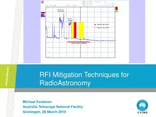
RFI Mitigation Techniques for RadioAstronomy Michael Kesteven Australia Telescope National Facility Groningen, 28 March 2010
Introduction • The issues • RFI-free environments • Blanking • RFI cancellation • The low RFI levels problem • The large dataset problem • Prospects RFI mitigation. Groningen, 2010
Introduction In the past decade a number of RFI mitigation techniques have been trialled and shown to work. Yet few observatories have on-line RFI mitigation installed. Has its time now arrived, perhaps? RFI mitigation. Groningen, 2010
There is no universal solution • Different sources of RFI • TV/Communications • Satellites • Observatory-based • Different types of Telescopes • Single dish • arrays • Different observing regimes • Low frequency; high frequency • VLBI • Pulsars • Spectral line • Continuum RFI mitigation. Groningen, 2010
The ITU RA-769 argument A.R.Thompson provided a useful framework to describe the impact of RFI. Of interest here is the link between the observation mode and the RFI levels. Recognise that RFI entering the main beam of a telescope (LOFAR apart) is generally a lost cause. Pitch the debate at RFI in the far sidelobes - at the level corresponding to a 0 dBi gain. RFI mitigation. Groningen, 2010
Single Dish Operation Natural defences are few antenna sidelobes (0 dBi gain) Mitigation techniques work well adaptive filters blanking Datasets are modest (relatively speaking) detailed probes over the entire dataset are realistic Vulnerable to low level interference RFI mitigation. Groningen, 2010
Arrays Natural defences are better: antenna sidelobes phase tracking decorrelation delay decorrelation (continuum observations) spatial resolution Mitigation techniques less well developed Datasets could become huge Some advanced techniques may not be realistic in the near term RFI mitigation. Groningen, 2010
Current response to RFI • Flag/blank post-detection data. • Retune the receiver to an adjacent frequency • Tolerate it • Reschedule the observations RFI mitigation. Groningen, 2010
The Challenge We need machinery to reduce the impact of RFI which is damaging the astronomer’s data. • It should be automatic, reliable and robust. • It should not introduce artefacts which mimic real results. • The cost of applying the machinery should be predictable. • The cost should be less than the cost of doing nothing. (cost : $, science, time) RFI mitigation. Groningen, 2010
Mitigation Options Pro-active mitigation : Avoidance Remove the RFI at source. Re-active mitigation : Remove the RFI from the data Blank those parts of the astronomical data space which contain RFI ---- excision. Identify and remove the RFI while leaving the astronomy untouched --- cancellation. RFI mitigation. Groningen, 2010
Avoidance no RFI to mitigate • Remote Locations • Regulation • Spectrum Management • Radio quiet zones • Good observatory practice • Discipline • Good design • Maintenance • Constant monitoring RFI mitigation. Groningen, 2010
Blanking, Flagging This is the current mitigation strategy of choice. It is attractive to observers because it is simple and its consequences are predictable: • The loss in sensitivity is related to the amount of data discarded. • The effect on the image quality can be estimated. • It is straightforward in its implementation, and can easily be automated. RFI mitigation. Groningen, 2010
Pulsed interferer (~msec) Time Radiometer integration period (~msec) Excision • Requirements: • The RFI events occupy a small fraction of the data space. • Each RFI event has to be detectable – needs INR > 1 in small number of samples. RFI mitigation. Groningen, 2010
Excision – Real Time blanking • Given the mean and rms of good data, define RFI to be those samples above a threshold (= r*rms) • Need to buffer some small number of data samples in order to be able to distinguish good from bad. • The buffer allows you to apply some intelligence: determine the local mean and rms in order to identify the outliers. • The buffer allows further options – one could blank a known pulse shape, for example. RFI mitigation. Groningen, 2010
Implementations A number of observatories have built hardware, on-line blanking devices. • Arecibo, for example, addresses the serious RFI from neighbouring radar. The known timing details of the pulsing assists the blanking trigger. • WSRT have demonstrated an impressive unit built around digital processing boards which, amongst in many capabilities, can provide on-line blanking. RFI mitigation. Groningen, 2010
Excision Post-correlation Blanking. Flag the data – instruct the downstream imaging/processing machinery to ignore the corrupt samples. This is the RFI-mitigation strategy of last resort. Tedious when done manually; automated scripts now available. When this is applied to the correlator output data, the minimum quantum of rejected data is the size of the correlator dump cycle. RFI mitigation. Groningen, 2010
ATCA – Middleberg Automated flagging RFI mitigation. Groningen, 2010
Frequency Blanking Discarding data in frequency space is a variant of this approach: modern high speed processing allows fine on-line spectral analysis, so that corrupted channels can be identified and excised. This is an option if the discarded fraction of frequency space is modest compared to the overall bandwidth. LOFAR includes this in its armoury. RFI mitigation. Groningen, 2010
Excision Issues The technique relies on the ability to detect RFI from a small number of samples (or from a priori information). It generally requires good INR. Long integrations with low INR will be compromised INR > 10 is a rough guide. There may be little to be gained by integration if the RFI is pulsed, as the INR is essentially based on a relatively small number of samples. (Periodic RFI is a separate case). Downstream processing should not be compromised. Care needed in defining the replacement sample. Discarding data in synthesis arrays will affect the (u,v) plane population and may therefore compromise the imaging quality. RFI mitigation. Groningen, 2010
Excision – Bottom line It can be a viable technique if the cost to science is modest. It depends on some prior definition of “badness”, and it depends on a low duty cycle. RFI mitigation. Groningen, 2010
Cancellation This is the more ambitious approach – identify and characterise the RFI; then remove just the RFI. This is a two-step process: • Characterise the RFI. • Subtract the RFI from the data – to give the astronomer an RFI-free dataset. RFI mitigation. Groningen, 2010
Cancellation -- How is the RFI identified? • Extract the RFI details from the data itself. • Point a reference antenna towards the RFI -- use adaptive filter. • Predict the RFI from published data (eg, GLONASS) – use software adaptive filter. RFI mitigation. Groningen, 2010
Questions: Mitigate on the data on-the-fly ? (each correlator dump) Or Mitigate on the entire observation. SNR is the issue with the first; Data volume the problem with the second. RFI mitigation. Groningen, 2010
Filter Variants • Image plane filtering • Spatial filtering • Null Steering • Cyclo-stationary filters • Adaptive filters RFI mitigation. Groningen, 2010
Clean/self-calibration filter (Cornwell-NRAO) Identify the RFI in the imaging stage. Apply self-calibration to the RFI. Remove the RFI. Stationary RFI will map to the pole. The self-calibration operates simultaneously in two areas : - The astronomical target; - The RFI which is stationary with respect to the observatory. The self-calibration accounts for the phasing and amplitude variations. It requires the data to be sampled much faster than the astronomical target would require. RFI mitigation. Groningen, 2010
Cornwell – 327 MHz. No Filtering Filter active RFI mitigation. Groningen, 2010
Spatial Filtering • Each object within the field of view of the array will add a specific signature to the full set of correlation products between the antennas. • An eigenvalue decomposition of the product matrix will isolate the strongest sources. • A projection operation can then remove the RFI sources. • This scheme has long history, most recently successfully demonstrated in the LOFAR trials. RFI mitigation. Groningen, 2010
The LOFAR snapshot variant • Within each widefield (whole sky) snapshot identify and remove the RFI point sources (as found by spatial filtering). This cleans the snapshot down to sky noise. 2. Stacking the sky-aligned snapshots builds the SNR on the astronomical objects while dissolving the remaining RFI. RFI mitigation. Groningen, 2010
This scheme is best suited to low frequency arrays (LOFAR) There are problems at higher frequencies, where very short correlator cycle times are required. The computing load for a detailed spatial filtering operation may be a limiting factor. RFI mitigation. Groningen, 2010
Cyclostationary Filters • The concept here is to identify the RFI by its temporal signature, cyclostationarity. This attribute is specific to RFI. • The classical spatial filtering matrix is replaced by a variant which is matched to a cyclic frequency. • The projection operation then proceeds as before, to remove the RFI. • This scheme has had some initial (promising) trials on LOFAR. RFI mitigation. Groningen, 2010
Null Steering The ATA is an array of 42 antennas that includes a beamformer mode of operation, each beam directed to a potential target. This opens the possibility of adjusting the beamformer weights to position nulls in the direction of known RFI sources – fixed or mobile. Wide-band nulls may be required (and have been demonstrated). The process works well, but has serious implications for the bandwidth of the phase tracking machinery. RFI mitigation. Groningen, 2010
Adaptive Filters These have been applied to : • Single Dish • Arrays The starting point is to obtain a copy of the RFI. We manipulate this copy to match the RFI in the data – the function of the adaptive filter. We then subtract the modified copy from the data. RFI mitigation. Groningen, 2010
Cancellation Real-time adaptive filter RFI mitigation. Groningen, 2010
Cancellation. Issues with the real-time filter It requires modest INR. Averaging at the correlation step helps. It can cope with multi-pathing, but not with multiple transmitters on the same frequency channel. With no RFI there is no added noise. Gain drops to zero. It adapts automatically to changes in the relative transmission path details. RFI mitigation. Groningen, 2010
Filter OFF Filter ON RFI mitigation. Groningen, 2010
Real-time adaptive filter Best suited to continuum single dish observations. Works well for pulsar and VLBI observations. It may not be suitable for spectral line observations, as the cancellation is not complete, and the residuals will mimic the original RFI spectrum. It could be difficult to implement in an array. RFI mitigation. Groningen, 2010
Post-Correlation adaptive filter • We combine three cross-products to get a good estimate of the interference in the astronomical channel. • No total power products in the cross-products, thus no bias. • Noise*RFI products are also removed. • The signal/noise is set by the ratio of Correlated RFI to noise products - RFI mitigation. Groningen, 2010
Single Dish – post-correlation Reference antenna Parkes 64m RFI mitigation. Groningen, 2010
Adaptive filters • Both real-time and post-correlation filters use the INR as a control factor – the filter switches off when INR <~ 1 This makes the filter robust. • Both filters subtract the correction term from the raw astronomy signal – they do not modify the astronomy. • The real-time filter provides attenuation, leaving some residual RFI power; • The post-correlation provides cancellation, with some added residual zero-mean noise. RFI mitigation. Groningen, 2010
Postcorrelation filter applied to an array • The Post-correlation adaptive filter has been successfully applied to an array. • A reference antenna provided the RFI copy. • This copy followed the same conversion chain and correlation path as all the antennas of the array. • Each baseline was corrected for RFI after computing a baseline-specific correction term. RFI mitigation. Groningen, 2010
Synthesis Array Filtering(ATCA, 1503 MHZ, 4 MHZ BW) RFI mitigation. Groningen, 2010
Before and after images RFI mitigation. Groningen, 2010
Post-correlation Adaptive filter - Issues • Still effective with low INR (to ~ 0.1) • Will require additional correlator capacity • Works well with single dish. • Works well with an array, but may require short correlator dump times RFI mitigation. Groningen, 2010
The Low INR problem The mitigation schemes generally work on short sections of data, but the astronomer works with the entire dataset. Low level RFI which may only show up in the final product is of concern. Future arrays may have too much data to allow RFI mitigation predicated on the entire dataset. The ASKAP, for example, needs to complete the processing on-the-fly, when in high-resolution spectral mode. RFI mitigation. Groningen, 2010
Conclusions The prospects look good at the low-frequency (LOFAR) end of the spectrum. The issue is less clear at SKA frequencies and above. A number of niche areas, such as VLBI and pulsars, look tractable. RFI mitigation. Groningen, 2010
Contact Us Phone: 1300 363 400 or +61 3 9545 2176 Email: enquiries@csiro.au Web: www.csiro.au Thank you Australia Telescope National Facility Michael Kesteven Phone: 61 2 9372 4544 Email: michael.kesteven@csiro.au Web: www.csiro.au/group
Array Adaptive Filter We introduce two additional “antennas” into the correlator system, R1 and R2, from the reference antenna. RFI mitigation. Groningen, 2010
Real-time & Post-Correlation Filters RFI mitigation. Groningen, 2010
Preliminaries types of RFI • Continuous (TV) likely to be an issue for long integrations, single dish. handled well by adaptive filters. • Impulsive (radar) amenable to blanking if strong. diluted and not important if low level (minor increase in Tsys) • Short term, strong (satellites) predictable, so precautionary measures possible. RFI mitigation. Groningen, 2010