Download

1 / 14
140 likes | 321 Vues
new - status of beam loading issues for the muon accelerator. Beam Loading. Energy transfer: W particle =e*U W cav,after =W cav,before - W particle W cav,before =W cav,after +P RFgen * T Stored energy scales with volume and EM field strength.

E N D
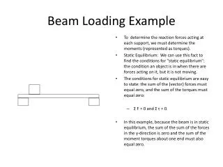
Beam Loading • Energy transfer: Wparticle=e*U Wcav,after=Wcav,before-Wparticle Wcav,before=Wcav,after+PRFgen*T Stored energy scales with volume and EM field strength. Power transferred from generator to cavity is Q factor dependent • NF Numbers : 1021/year of 107 sec at 50 Hz = 2*1012 muons at 50 Hz 201 MHz – 88 bunches per train = 2.3*1010 p / bunch in ~5 ns (7.7*109 p/bunch for 3 proton bunches, 4.6*109 p/bunch for 5 pb ) • Comparison with ILC 5*1013 particles / train in 1-4 s 1300 MHz - 1330-5640 bunches per train 1- 4.3*1010 p/ bunch~ 0.8ns
Energy gain of particles • NF linac - worst case – one proton pulse: • 17 MV/m , 0.7 m, transit time factor ~ 0.66 ~ 10 MV • ~ 1.6 pJ per particle and cavity ~ 37 mJ per bunch ~ 3.2 J per bunch train • ILC – best case: • 20 MV/m , 0.10 m, ~ 0.2 pJ per particle and cavity ~ 2-9 mJ per bunch ~ 12 J per bunch train
Energy stored in cavity Superfish :Energy stored in one 201 MHz cavity ~ 235 J
RF voltage drop • 201 MHz one proton bunch • Wcav = 235 J ; Ecav ~ 15-17 MV/m • => Energy gain per cavity ~ 10 MeV • Wcav = 37 mJ / bunch ; Wcav = 3.2J / bunch train • Vcav ~ 0.8 kV / bunch ; Vcav ~ 68 kV / bunch train • 1300 MHz • Wcav = 5 J ; Vcav ~ 20 MV • Wcav ~ 2-8 mJ / bunch ; Wcav = 12J / bunch train • Vcav ~ 20-80 kV / bunch
Energy spread • For one bunchtrain without RF correction - for three trains the effect is reduced by a factor of ~3.4 (blue values)
Beam Loading - conclusions • No issue for muon front end • Small (invisible) influence in Linac • In RLA and FFAG BL causes increase of energy spread and (slight) decrease of acceleration. (Is this acceptable ?) • 3 Proton bunch scenario & 100 s bunch (train) spacing will reduce the effect within a bunchtrain by a factor of ~3.4 and allow to refill cavity until next bunchtrain (~100 kW / cavity)) • Fast active phase shifters ? • Detuned cavities along linac ? But : P mode cavities leave not much space for RF phase & frequency manipulation without reducing the gradient or loss of long focussing….
Numerical model • Linac: Accelerating from 244 to 900 MeV consists according to base line and publications of 66 cavities. No average average energy gain par cavity is given in the baseline document but with the given numbers the required average energy gain is ~10MeV per cavity. From the energy gain the maximum field strength in the cavity can be calculated (assuming a length of 0.74 m for the cavityand a transit time factor of 0.6366) to be (10 MV/(0.75 m * 0.6366)=21 MV/m peak. (In some document an field of 15-17 MV/m is given which would not be sufficient to allow full acceleration.) • RLA1: Accelerating from 900 MeV to 3600 MeV within 4.5 passes. In the baseline document only the energy gain per cavity is given to be 12.75 MV. From other document it can be seen that the RLA1 linac consists of 24 Modules with 2 cavities each = 48 cavities producing the required total acceleration in the simplified model with an average energy gain of ~12.5 MeV. The electric field strength is then (12.5/(0.75 * 0.6366)=26.7 MV/m peak. It must be noted that this field strength seems to be very ambitious considering the frequency of 201 MHz. • RLA2: Accelerating from 3600 MeV to 12600 MeV within 4.5 passes. In the baseline document only the energy gain per cavity is given to be 12.75 MV. From other document it can be seen that the RLA2 linac consists of 80 Modules with 2 cavities each = 160 cavities producing the required total acceleration in the simplified model with an average energy gain of ~12.5 MeV. The electric field strength is then (12.5/(0.75 * 0.6366)=26.7 MV/m peak. • FFAG: The baseline states that the FFAG consists of a FODO lattice with 62 cells accelerating from 12600 MeV to 25000 MeV and an energy gain per cavity to be 12.75 MV. Based on these values it has been assumed that the RF system consists of 62 Modules with 2 cavities each = 124 cavities with an average energy gain of ~12.5 MeV per cavity accelerating the beam within 8 revolutions. Again the electric field strength is (12.5/(0.75 * 0.6366)=26.7 MV/m peak. This set up would leave no space for kickers etc. as each cell is filled, but with similar results 40 Modules with 3 cavities per module (the space would be available) could be used leaving the required space.
Total energy gain in muon accelerator Cases investigated : One bunch train no BL One bunch train BL 3 BT no BL 3 BT , BL no RF 3 BT, BL , 250 kW/C & 20 ms 3 BT, BL , 250 kW/C & 200 ms 3 BT, BL , 500 kW/C & 20 ms
and now some questions…. • For how little energy spread (and which “spread/shift/droop” do we mean? • How large is the final energy spread at FFAG extraction without beam loading? • Do we believe that 26.7 MV/m in a SC 200 MHz is realistic ? • How can we achieve a consistent BL document available for all on the web pages ? • It seems that 3 BT with 40 ms spacing at one 500 kW coupler per cavity is as good as 200ms spacing…. Considering the problems (proton driver, front end) so what is the best choice ?