Download
1 / 69
690 likes | 711 Vues
Status of the Muon System. Large Hadron Collider (LHC). Mont Blanc. Geneva. 7 TeV. 7 TeV. LHCb. CERN. ATLAS. CMS. 27km tunnel. ALICE. ATLAS, CMS, LHCb, ALICE. multi-purpose exp. dedicated. bunch. bunch. Proton -proton. 2835+ 2835 bunches/cycle 7.5m bunch separation (25ns)

E N D
Status of the Muon System Kащук A.П.Семинар
Large Hadron Collider (LHC) Mont Blanc Geneva 7 TeV 7 TeV LHCb CERN ATLAS CMS 27km tunnel ALICE ATLAS, CMS, LHCb, ALICE multi-purpose exp. dedicated Kащук A.П.Семинар
bunch bunch Proton-proton • 2835+2835 bunches/cycle • 7.5m bunch separation (25ns) • 1011 protons/bunch • Crossing rate 40 MHz • Luminosity 1034 cm-2sec-1 (project) • First 3 years at 5·1032 cm-2sec-1 • ~109 collisions/sec • 23 pp-interactions per bunch crossing High particle densities High requirements for the detectors Kащук A.П.Семинар
The LHC machine status 2005 March 2005: lowering of the magnetic dipole into the tunnel 1232 magnets, 8.33 Tesla, 15m long Operational temperature 1.9K LHC is the largest cryogenic system in the world Since 2005 in operation Kащук A.П.Семинар
CP Violation (worldwide quest) LHCb CKM-best LHC P940 E787/949 BTEV ATLAS KEK / J-PARC Super-Bell ? NA48 CLEO-c Super-BABAR ? (?) Kащук A.П.Семинар
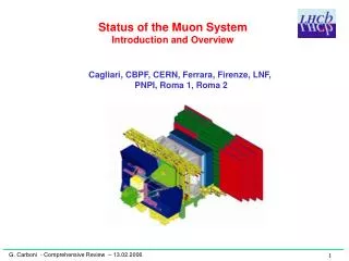
Muon Detectors RICH-2 Iron Filters Magnet RICH-1 Si Vertex Detector 5 Muon Stations Station M3 R1-R4 MWPCs of one quadrant LHCb Muon System Multi Wire Proportional Chambers (MWPC) technology: • Fast muon triggering • Muon identification 5 Muon Stations, 4 Regions / Station 120000 channels Detector area: 435m2 EM Calorimeter Hadron Calorimeter Inner Tracker: Si Outer Tracker: Drift Tubes 11MCHF Kащук A.П.Семинар
LHCb spectrometer Kащук A.П.Семинар
Tasks of the Muon System: 1 High-Pt L0 trigger using M1, M2, IP PT > 5 GeV/c 2 Muon identification using M1-M5off-line PT resolution 20% Kащук A.П.Семинар
Status of the Muon System Contents of the seminar • MWPC of various types and main characteristics • Efficiency and time resolution • Cluster-size, cross-talks, multiple hits • Tasks of years 2005-2006: mass-production • MWPC conditioning technique • New task of year 2006: detector ‘dressing’ Front-end electronics - installation problems Kащук A.П.Семинар
MWPC mass-production (2005-2006) 600 chambers are produced in Italy (3 centers): Frascati Ferrara Firenze 600 chambers are produced at PNPI (2 centers): 200 M2R4 200 M3R4 200 M4R4 Σ=1400 ~60% done 200 at CERN Help: Roma1, Roma2, Potenza, Cagliari Kащук A.П.Семинар
Quadri-gap MWPC MWPC Quadri-gap=Double Bi-gap MWPC Gap size: 5 mm (symmetric) Gas mixture: Ar/CO2/CF4 (40:55:5) Wire: Gold-plated Tungsten, 30 μm Ø, 250 to 310 mm wire length Wire spacing: 2 mm Mechanical tension: 65 g Operational HV= 2.650 kV Field on wires: 262 kV/cm Field on cathodes 6.2 kV/cm Average gas gain: G ≈ 50 000 Specific design feature Re-opened for regions R1, R2 Glued for other regions Kащук A.П.Семинар
Triple GEM (Gas Electron Multiplier) • Bi-gap Triple GEM (station M1R1) • 12 chambers of an active area 20x24 cm2 each • 50um Copper coated Kapton foil perforated by a high • density of holes ( 70 μm in diameter, pitch of 140 μm ) • segmented on 6 sectors • Pad size 10 mm in X and 25 mm in Y direction • Gap size: 3+1+2+1 mm • Honeycomb panels • Total material 7.2%X0 (Bi-gap) Bi-gap Triple GEM Kащук A.П.Семинар
Historical review: F.Sauli, NIM A368 (1997) 531 Triple-GEM detector PNPI priority since 1998 Препринт 2283, EP-69-1998 B.Bochin, A.Kashchuk,V.Poliakov LHCb Note 98-068, 1998 Ar-CO2 gas mixture doped by alpha-particles Kащук A.П.Семинар
Triple-GEM Double-GEM Discharges induced by α(400keV) The Triple-GEM overcomes Double-GEM on discharge limit Crucial in practice Kащук A.П.Семинар
Historical review on Triple-GEM PNPI 1999 5.9ns time resolution (rms) in Ar(70)CO2(30) mixture measured on MIP at PSI in 1999 Kащук A.П.Семинар
What new has been developed by our Italian colleges in GEM-detector? Frascati Cagliari • GEM foil stretching of 30 kg per side, ~1 kg/cm • It gives a bending of 100 μm on central region • when a distributed load of 100 g is applied • It allows to reduce induction gap to 1 mm • Gas mixture choice • Practical detector optimization • Very good aging study Notice: induction gap 1mm is impossible in the symmetric MWPC due to efficiency losses Kащук A.П.Семинар
Efficiency(beam T11, CERN PS, 2002) Bi-gap Triple-GEM at threshold 3 fC 99% Efficiency in 25 ns Op. gas Kащук A.П.Семинар
GEM Aging Results Gas flux 200 cc/min HF etching No deposits Gas flux 20 c/min Increasing operational voltage compensates this effect Kащук A.П.Семинар
Detector Simulation Tools Kащук A.П.Семинар
MWPC efficiency and time resolution Kащук A.П.Семинар
Primary Ionization:HEED 10. 5 clusters/mm at 7GeV 2.4 electrons/cluster Kащук A.П.Семинар
Comparison measurements with simulationvery satisfactory MWPC Operational range Kащук A.П.Семинар
MWPC of various types:Wire Readout Bi-gap is shown for simplicity wired OR (double signal) I1 I2 R4 of Stations M2-M5 (Quadri-gap) I1 R4 of Station M1 (Bi-gap) I2 Bi-gap: wired OR of single gaps Quadri-gap: logical OR of 2 Bi-gaps Kащук A.П.Семинар
Anode Wire Efficiencyin 20ns time windowBeam T11, CERN PS Wired OR Wired OR 95% 2.43kV 99% 2.55kV Bi-gap eff. Quadri-gap eff. 95% 2.4kV 99% 2.5kV Bi-gap eff. Quadri-gap eff. Kащук A.П.Семинар
Anode Wire Efficiency in 20ns for different detector capacitancesBeam T11, CERN PS Kащук A.П.Семинар
Single Cathode Readout(CPC-SCRO) Regions R1-R3 =22 Single gap is show for simplicity Capacitors are shown on one pad for simplicity Stations M2-M5 (Quadri-gap) Half signal w.r.t. WPC Kащук A.П.Семинар
Cathode Pad Efficiency in 20ns time windowBeam T11, CERN PS Wired OR Wired OR 95% 2.42kV 99% 2.54kV Bi-gap eff. Quadri-gap eff. Bi-gap eff. Quadri-gap eff. 95% 2.45kV 99% 2.56kV Kащук A.П.Семинар
Cluster size, Cross-talks, multiple hits Have influence to L0-trigger efficiency Kащук A.П.Семинар
Cross-talks are <5% everywhere in and out of 50ns time window (better in 20ns time window) Cluster-size, Cross-talks, Multiple hitsin 50ns time window(beam X7, CERN SPS) Kащук A.П.Семинар
I1+I2 Double Cathode Readout(CPC-DCRO) Det.GND (very pure) Guard Cathode 1 HV I1 Rdamp C=1nF R=100k Anode wire I1+I2 I2 Cathode 2 Guard Single gap is show for simplicity One readout Amp. is shown for simplicity. Ramp R1, R2, R3 of Station M1 (Bi-gap) R1 of Stations M2, M3 (Quadri-gap) Double signal similar to WPC Kащук A.П.Семинар
1.8I Asymmetric Single Cathode Readout(CPC-SCRO) Det.GND Det.GND Cathode 1 HV 0.2I C R=100k Anode wire strip Rejected 2I 1.8I Cathode 2 Guard One gap and one readout Amp. are shown for simplicity Ramp R1 of Station M1 (Bi-gap) Kащук A.П.Семинар
Efficiency and Cluster size vs. HVAr(40)CO2(40)CF4(20) Threshold ~15% mean signal (6fC) Threshold ~20% mean Signal (7fC) Kащук A.П.Семинар
Triple GEM shows better cluster size Induction gap 1mm Threshold ~ 3fC Kащук A.П.Семинар
Cross-talks along wires in CPC dominate SCRO, DCRO Cpad Cpad N pads 100% X-talks at N=2 Cross-talks depend on segmentation and not depend on capacitors Kащук A.П.Семинар
Blocking capacitor has to be installed to fix potential on wire strip and improve ratios nCx Cx Cx Cx Cx 2N+n ‘elementary’ capacitors of Cx Cross-talks are mainly specified by the ratio Kащук A.П.Семинар
Attention: resonance… with discrete blocking capacitor Parasitic L Discrete C Damping: Loop • An effective blocking capacitor is reduced with damping increasing cross-talks • Optimization is needed A.Kashchuk LHCb Note Kащук A.П.Семинар
GEM-foil i Pad GEM-foil i BC Pad GEM: Blocking Capacitor • Signal current flows to GND through the capacitance between the last GEM foil and Pads, but how returns? • With Blocking Capacitor the most part of the current returns through the BC no more through the electronics • A small resistor in series is needed to damp possible oscillations • The BC has been introduced in the setup soldering a discrete capacitance between the HV pin of the GEM3 and GND i Kащук A.П.Семинар
GEM: cross-talks and multiple hits Triple GEM Gain=20000 13500 events A. B. Two peaks in the time spectra: Direct Induction Due to cross-talk coupling between the last GEM-foil and all pads Kащук A.П.Семинар
GEM:Blocking Capacitor effect Without BC Gain=20000 Cross-talks reduction ~100 With BC 700 pF+ 8 Ω With BC 700 pF+ 8 Ω Without BC 13240 events 33110 hits in the second peak With BC 13560 events 354 hits in the second peak Kащук A.П.Семинар
Time-shifted cross-talks … electronics Sensitivity (mV/fC) -Qin +Qin In Analog Digital BLR-defect 50ns/div Increased delay Normal delay Kащук A.П.Семинар
MWPC conditioning of the new chamber Surface treatment A.Kashchuk LHCb Note 2005-096 Kащук A.П.Семинар
The fields on surface in an ideal MWPCat HV=2.75kV Cathode Wire Traditional HV-training at positive voltage has serious disadvantages Kащук A.П.Семинар
Wire surface treatment at reversed voltage by ion bombardment Current versus anode-cathode voltage (measurements, GIF) Townsend multiplication in gas Field emission Ion bombardment From/To full area Operation point for wire conditioning • Operation voltage point: HVmax=-2340V. • Average time ~ 48 hours Kащук A.П.Семинар
time 10 min current reduction in time Monitoring during wire conditioning • Time scale ~ 10 minutes after voltage increment • at the beginning of procedure, e.g. HV=-2000V • Current is reduced each time by factor of 10 Table of voltages, current limits and time Repeat, if… • 48 hours at constant HVmax=-2340V • Local field is reduced dramatically • Current is reduced by factor of … many order of magnitude • MWPC has been conditioned • if no emission at predefined voltage t=0 t=3h t=48h Kащук A.П.Семинар
Results of wire conditioning • ~ 100% yield of good chambers • Conditioning time in average at HVmax=-2340V: ~ 48 hours at operational gas: Ar(40)CO2(55)CF4(5) • Conditioning rate: 1 chamber per day per operator at 2 places • No discharges have been observed at maximum current 10μA • Less attention is needed • Computer automated process (implemented at CERN) • First ramp-up at positive HV: ~ 15 minutes to reach operational HV=+2650V and even critical HV=+2900V after such conditioning (GIF well helps in some cases) Definition: Kащук A.П.Семинар
Cathode quality tests and cathode conditioning performed on Gamma Irradiation Facility (GIF) at CERN to have many ions covering full cathode surface HV=+2750V Our tests show: An ability of MWPC to operate at high gamma background is strongly depends on the cathode quality Kащук A.П.Семинар
Unexpected Measurements on Gamma Irradiation Facility (GIF) at CERN Building-up effect 8 gaps (2 chambers) are shown ~ 10 minutes scale Kащук A.П.Семинар
Experimental facts: • No emission on solid cathodes • Segmented cathodes show emission in ~50% of chambers Possible model Thin Film Field (Malter-like) Emission Emission most likely from the area between cathode pads Reason: Imperfect cathode cleaning, remaining insulating film (dirt) Kащук A.П.Семинар
Emission physics Fowler-Nordheim equation: current density vs. field const2 const1 Ref:R.H.Fowler and L.W.Nordheim, Proc.Roy.Soc. London, A119(1928) 173. Here J(E) [A/cm2] has been multiplied by gas gain FN-Theory The ideal field on cathode has to be: Close to our case… E – local field [V/cm] Kащук A.П.Семинар