Download
1 / 21
210 likes | 417 Vues
The New Alarm Display Software for the RHIC Control Room Peter F. Ingrassia Main Control Room Group Leader Collider-Accelerator Department and S. Nemesure, L. Hammons, N. Kling, T. Shrey 9 August, 2012. Abstract http://www-conf.slac.stanford.edu/wao2012/sessionAbstracts.asp.

E N D
The New Alarm Display Software for the RHIC Control Room Peter F. Ingrassia Main Control Room Group Leader Collider-Accelerator Department and S. Nemesure, L. Hammons, N. Kling, T. Shrey 9 August, 2012
Abstracthttp://www-conf.slac.stanford.edu/wao2012/sessionAbstracts.aspAbstracthttp://www-conf.slac.stanford.edu/wao2012/sessionAbstracts.asp • The Alarm Display for the new RHIC Control Room has undergone a radical reworking. While keeping some of the existing software infrastructure the display adds new database driven features to assist operators to track and manage alarms. A key feature of the application facilitates communication from operator to operator and operator to system specialist of the status e.g. "work in progress" of individual alarms. A new summary display, borrowed from KEK, helps operators pinpoint "distressed" accelerators. This talk will summarize the new features of the alarm display and will review operator experience with the application after two years of use.
What will be covered in this talk: • Focus on the “Communication” Features of the application • Operator to Operator • Operator to Specialist • Specialist to Operator • Micro review of System Infrastructure • Summary Display • Alarm Tracking • Alarm Annotation • Response Instructions • Summary - Operator Experience
Collider Accelerator Department at Brookhaven National Laboratory
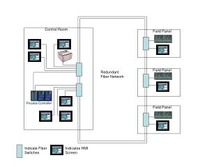
Alarm System Infrastructure • Code/manager running on fec detects alarm and sends to “Notification server”. • Notif server determines if alarm is real or a diagnostic not relevant to operators • Notif server sends alarm to the Alarm Receiver which sends it to alarm displays. • Applications send alarms directly to the Alarm Receiver Device Front end Computer Notification Server Alarm Receiver Application Alarm Displays
Summary Display (a la KEK ca 2003) • Summary allowed the reduction of Alarm Receivers from two to one • 7 Machines + one “other” • Color represents the alarm level of the most severe alarm • Number in the colored field represents the number of NEW alarms • Number in parenthesis refers to number of SEEN alarms • Summary Display is interactive – may spawn an Alarm Display FILTERED by “machine”
Jargon -- Alarm (Severity) Levels • A Note on Alarm Severity Levels • Throughout the Alarm System, alarms are tagged with a severity level. This severity level affects the way alarms are displayed and the way they are managed. These severity levels are based on a standard employed at SLAC (ca 1992). The levels range from 1 to 5 with 5 being the most severe. The levels are defined as follows. • Level 1 Warning, includes power supplies going out of tolerance or tripping off. • Level 2 Interlock, indicates safe interruption due to the action of an interlock. • Level 3 Potential Equipment Damage, includes water leaks, vacuum problems, and high temperature alarms. • Level 4 Potential Environmental Impact (not immediately life threatening), includes tritiated water leaks and high radiation fields. • Level 5 Potential Life Threatening, includes very high radiation fields.
Jargon -- Alarm (Resolution) States • New • Alarm has arrived and has not been investigated by an operator. • Seen • Operator has detected the alarm and assumes some responsibility to follow up. • Assigned • Operator cannot resolve the alarm independently. Alarm is forwarded to another group. • Deferred • Investigation is complete but resolution is not immediately possible (ring access, extensive work required). • Orphaned • Alarm is expected to persist. It is not expected that anything will be done about the alarm any time soon. • Cleared • Alarm has been resolved and is no longer visible on alarm screen (latched alarms may persist).
Alarm Tracking • Alarm Tracking • Follow Alarm Life Cycle • state • Transfer Over Shift Change • owner/user • Previous Alarm History • Timestamp
Alarm Tracking – Data base view • Fields • Time stamp • Alarm • Level • State • Description • Action • Machine • Device Type • System • Location • Annotation • User Name
Example -- alarm response instructions displayed on a webpage
Summary - Operator Experience • Annotation Feature is “fabulous” • “Ownership” avoided • operators misunderstood short term intention of ownership. • Labor involved • Some operators used the features more than others • Not all alarms required annotation • Operators developed a good understanding of short tem alarms which need not be annotated • One year of experience -- more acceptance needed