Download

1 / 30
310 likes | 637 Vues
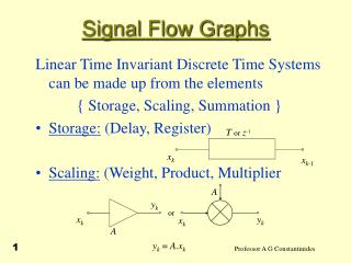
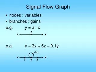
2.7 Block Diagram 、 signal graph and mason rule. Block Diagram is a kind of tool showing component performance,system construction and signal direction 。. 2.7.1 Block Diagram element ( 1 ) Block :shows function relation between output and input 。.

E N D
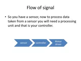
2.7 Block Diagram、signal graph and mason rule Block Diagram is a kind of tool showing component performance,system construction and signal direction。 • 2.7.1 Block Diagram element • (1)Block :shows function relation between output and input。 Signal line:have arrow which shows signal flow direction, signal nearby. (2)comparison point(Summing Point) 2 or many signal addition or reduction。 “+” addition ,“-” reduction 。“+”can be ignored。
note:comparison signal must have same unit。 (3) Branch Point (output point、measuring point) note:same position has same signal。
2.7.2 some concepts and terms (1)forward path TF—assuming N(s)=0 when feedback interrupted,the ratio of output C(s) and input R(s) ,or C(s) and E(s) (2)feedback path TF assuming N(s)=0 the ratio of chief feedback signal B(s) and output C(s) 。
(3) Open-loop Transfer Function(assuming N(s)=0). when feedback interrupted, the ratio of chief feedback signal B(s) and error E(s) 。 (4) Closed-loop Transfer Function(assuming N(s)=0) the ratio of output C(s) to input R(s) 。 Because of: modify ** please remember That is
(5)error TF(assuming N(s)=0) the ratio of error E(s) to input R(s)。 substitute To equ. Above,canceling G(s) :
(6) TF of output to interference TF assuming R(s)=0 ** Using **,get: Fig.2-18
(7) TF of error to interference assuming R(s)=0 ** fig2-19 Using **,get:
From addition,when both input R(s)and interference act on a system,its output and error are: 2.7.3 drawing block diag. (1)considering load effect,write the each part's differential equ. or TF,express in block diag.. (2) according to the signal direction,use the signal line to link every block. System block diag. is also a kind of system's math model.
Exam.2-8 drawing RC circuit block diag. . From fig.2-20,using kichihoff rule: Take Laplace transform: fig2-20
combine(b)and (c) get (d),fig.(d) is RC network block diag..
drawing RC circuit block diag. . (1)according to circuit rule, and write differential equ. and its Laplace transformation, also can directly draw out circuit calculating diagram ( b)(2) according to 4 listing formulas make block diagram;(3) according to signal flow direction,link the every block one by one. Exam.2-9 From the fig., R2-C2 iis the load of R1-C1,affects R1-C1output voltage ---load effect.
If connect a insulation enlarger of high resistance between two R- C , such as the fig 2-22 shown,Then the block diagram is shown as diagram( b).
2.7.4 block diam. reduction——equivalent transform in order to write TF,it is necessary to transform block diam..the transformation must obey a principle, namely the transformation keeps TF constant.In control system, any complicated system is mainly composed of series,parallel and feedback. (1)series Fig 2-23 series
Characteristics:the output forward is the input backward N:series no. conclusion:The equivalent TF is the products of all the TF.。
(2)parallel Fig 2-24 parallel Characteristics:every component input is the same R(s),output C(s) is the sum of all the output.
n parallel no,including “-” 。 conclusion:The equivalent TF is the sum of all the TF.。
(3)feedback Fig 2-25 feedback (4)comparison point and branch point(output)move
amplificationshrink shrink amplification Fig 2-26 comparison point move
left right shrink amplification amplificationshrink Fig 2-27 branch point(output)move
C ( s ) C(S) C ( s ) C ( s ) R ( s ) R ( s ) ± ± + + C ( s ) P(s) Q(s) Q ( s ) P ( s ) C(S) C ( s ) C ( s ) (5)neighboring comparison point and branch point(output)move forwardback forwardback Fig 2-26 neighboring point move
G2 G1 R(s) C(s) + ( a ) G1 + + – H Exm. Solve C(s)/R(s) in the system shown in following diag. G2 R(s) C(s) + G1 + + - H
C(s) G1 1+ R(s) G2 (b) 1+G1H G1 R(s) C(s) G1+G2 (c) 1+G1H exam. Solve C(s)/R(s) in the system shown in following diag. R(s) C(s) G1 G2 + + + +
R(s) C(s) G1 G2 (a) + + + + R(s) C(s) G1+1 G2 (b) + + R(s) C(s) G1G2+G2+1 (c)
Exam.2-10 Give TF C(s)/R(s)in fig. 2-28 system This is a system of many crossing tracks .if do not transform it,it is difficult to reduce with series, parallel and feedback.method is as follows. Fig 2-28
series and parallel feedback
Exam 2-11 Simplify fig.2-9.
simplification hints: • A move backward • B move forward • 1 and 2 move。 Fig 2-29 reduction process
Check methods: assure forward path TF is a constant; assure feedback loop TF is a constant; Note :symbol change Homework: 2-17