Download
1 / 71
720 likes | 911 Vues
Quiz 1. The following represents two signals in time and frequency domain. 1) Explain the differences in the frequency domain figures. 2) If the channels we are using are base band channels, which signal requires a higher bandwidth channel to be transmitted successfully? Why?.

E N D
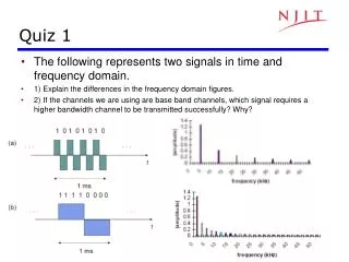
Quiz 1 • The following represents two signals in time and frequency domain. • 1) Explain the differences in the frequency domain figures. • 2) If the channels we are using are base band channels, which signal requires a higher bandwidth channel to be transmitted successfully? Why?
Note 3: Digital Transmission Fundamentals Digital Representation of Information
Bits, numbers, information • Bit: number with value 0 or 1 • n bits: digital representation for 0, 1, … , 2n • Byte or Octet, n = 8 • Computer word, n = 16, 32, or 64 • n bits allows enumeration of 2n possibilities • n-bit field in a header • n-bit representation of a voice sample • Message consisting of n bits • The number of bits required to represent a message is a measure of its information content • More bits → More content
Block Information that occurs in a single block Text message Data file JPEG image MPEG file Size = Bits / block or bytes/block 1 kbyte = 210 bytes 1 Mbyte = 220 bytes 1 Gbyte = 230 bytes Stream Information that is produced & transmitted continuously Real-time voice Streaming video Bit rate = bits / second 1 kbps = 103 bps 1 Mbps = 106 bps 1 Gbps = 109 bps Block vs. Stream Information
Transmission Delay Use data compression to reduce L Use higher-speed modem to increase R Place receiver closer to reduce d • L number of bits in message • R bps speed of digital transmission system • L/Rtime to transmit the information • tprop time for signal to propagate across medium • d distance in meters • c speed of light (3x10⁸ m/s in vacuum) Delay = tprop + L/R = d/c + L/R seconds
Compression • Information usually not represented efficiently • Data compression algorithms • Represent the information using fewer bits • Lossless: original information recovered exactly • E.g. zip, rar, compress, GIF, fax • Lossy: recover information approximately • JPEG • Tradeoff: # bits vs. quality • Compression Ratio #bits (original file) / #bits (compressed file)
W W W W H H H H Color Image Red component image Green component image Blue component image Color image = + + Total bits = 3 H W pixels B bits/pixel = 3HWB bits Example: 810 inch picture at 400 400 pixels per inch2 400 400 8 10 = 12.8 million pixels 8 bits/pixel/color 12.8 megapixels 3 bytes/pixel = 38.4 megabytes
Th e s p ee ch s i g n al l e v el v a r ie s w i th t i m(e) Stream Information • A real-time voice signal must be digitized & transmitted as it is produced • Analog signal level varies continuously in time
7D/2 5D/2 3D/2 D/2 -D/2 -3D/2 -5D/2 -7D/2 Digitization of Analog Signal • Sample analog signal in time and amplitude • Find closest approximation Original signal Sample value Approximation 3 bits / sample Rs = Bit rate = # bits/sample x # samples/second
Bit Rate of Digitized Signal • Bandwidth WsHertz: how fast the signal changes • Higher bandwidth → more frequent samples • Minimum sampling rate = 2 x Ws (the Nyquist rate) • Representation accuracy: range of approximation error • Higher accuracy → smaller spacing between approximation values → more bits per sample
Telephone voice Ws = 4 kHz → 8000 samples/sec 8 bits/sample Rs=8 x 8000 = 64 kbps Cellular phones use more powerful compression algorithms: 8-12 kbps CD Audio Ws = 22 kHertz → 44000 samples/sec 16 bits/sample Rs=16 x 44000= 704 kbps per audio channel MP3 uses more powerful compression algorithms: 50 kbps per audio channel Example: Voice & Audio
30 fps Video Signal • Sequence of picture frames • Each picture digitized & compressed • Frame repetition rate • 10-30-60 frames/second depending on quality • Frame resolution • Small frames for videoconferencing • Standard frames for conventional broadcast TV • HDTV frames Rate = M bits/pixel x (WxH) pixels/frame x Fframes/second
176 QCIF videoconferencing 144 at 30 frames/sec = 760,000 pixels/sec 720 Broadcast TV at 30 frames/sec = 10.4 x 106 pixels/sec 480 1920 HDTV at 30 frames/sec = 67 x 106 pixels/sec 1080 Video Frames
Transmission of Stream Information • Constant bit-rate (CBR) • Signals such as digitized telephone voice produce a steady stream: e.g. 64 kbps • Network must support steady transfer of signal, e.g. 64 kbps circuit • Variable bit-rate (VBR) • Signals such as digitized video produce a stream that varies in bit rate, e.g., according to motion and detail in a scene • Network must support variable transfer rate of signal, e.g., packet switching or rate-smoothing with constant bit-rate circuit
Stream Service Quality Issues Network Transmission Impairments • Delay: Is information delivered in timely fashion? • Jitter: Is information delivered in sufficiently smooth fashion? • Loss: Is information delivered without loss? If loss occurs, is delivered signal quality acceptable? • Applications & application layer protocols developed to deal with these impairments
Note 3: Digital Transmission Fundamentals Why Digital Transmission?
Transmitter Converts information into signalsuitable for transmission Injects energy into communication medium or channel Telephone converts voice into electric current Modem converts bits into tones Receiver Receives energy from medium Converts received signal into a form suitable for delivery to users Telephone converts current into voice Modem converts tones into bits Transmitter Receiver Communication channel A Transmission System
Analog transmission: all details must be reproduced accurately Sent Analog vs. Digital Transmission Distortion Attenuation Received Digital transmission: only discrete levels need to be reproduced Received Sent Distortion Attenuation Simple Receiver: Was original pulse positive or negative?
Communication Channel Pair of copper wires Coaxial cable Radio Light in optical fiber Light in air Infrared Transmitted Signal Received Signal Transmitter Receiver Communication channel Transmission Impairments • Transmission Impairments • Signal attenuation • Signal distortion • Spurious noise • Interference from other signals
Transmission segment . . . Destination Repeater Source Repeater Analog Long-Distance Communications • Each repeater attempts to restore analog signal to its original form • Restoration is imperfect • Distortion is not completely eliminated • Noise & interference are only partially removed • Signal quality decreases with # of repeaters • Communication is distance-limited • Still used in analog cable TV systems • Analogy: Copy a song using a cassette recorder
Transmission segment . . . Destination Regenerator Source Regenerator Digital Long-Distance Communications • Regenerator recovers original data sequence and retransmits on the next segment • Can design so such that the error probability is very small • Then each regeneration is like the first time! • Analogy: copy an MP3 file • Communication is possible over very long distances
Advantages of Digital over Analog • Digital regenerators eliminate the accumulation of noise that takes place in analog systems • It is thus possible to provide long-distance transmission that is nearly independent of distance • Digital transmission systems can operate with lower signal levels or with greater distances between regenerators • This translates into lower overall system cost • Digital transmission facilitates the monitoring of the quality of a transmission channel in service • Nonintrusive monitoring is much more difficult in analog transmission systems • Digital transmission systems can multiplex and switch any type of information represented in a digital form • Digital transmission also allows networks to exploit the advances in digital computer technology • Error correction, data encryption, various types of network protocols
1 0 1 1 0 1 +A T 0 2T 4T 5T 6T 3T -A Digital Binary Signal Bit rate = 1 bit / T seconds For a given communication medium: • How do we increase transmission speed? • How do we achieve reliable communications? • Are there limits to speed and reliability?
Objective: Maximize pulse rate through a channel, that is, make T as small as possible Pulse Transmission Rate Channel t T t • If input is a narrow pulse, then typical output is a spread-out pulse with ringing • Question: How frequently can these pulses be transmitted without interfering with each other? • Answer: 2 x Wc pulses/second (Nyquist rate), where Wc is the bandwidth of the channel
A(f) 1 f 0 Wc Bandwidth of a Channel • If input is sinusoid of frequency f, then • output is a sinusoid of same frequency f • Output is attenuated by an amount A(f) that depends on f • A(f)≈1, then input signal passes readily • A(f)≈0, then input signal is blocked • Bandwidth Wc is range of frequencies passed by channel X(t) = a cos(2pft) Y(t) = A(f) a cos(2pft) Channel Ideal low-pass channel
Multilevel Pulse Transmission • Assume a channel of bandwidth Wc, and transmit 2 Wc pulses/sec (without interference) • If pulses amplitudes are either -A or +A, then each pulse conveys 1 bit, so Bit Rate = 1 bit/pulse x 2Wc pulses/sec = 2Wc bps • If amplitudes are from {-A, -A/3, +A/3, +A}, then bit rate is 2 x 2Wc bps • By going to M = 2m amplitude levels, we achieve Bit Rate = m bits/pulse x 2Wc pulses/sec = 2mWc bps In the absence of noise, the bit rate can be increased without limit by increasing m
Noise & Reliable Communications • All physical systems have noise • Electrons always vibrate at non-zero temperature • Motion of electrons induces noise • Presence of noise limits accuracy of measurement of received signal amplitude • Errors occur if signal separation is comparable to noise level • Bit Error Rate (BER) increases with decreasing signal-to-noise ratio • Noise places a limit on how many amplitude levels can be used in pulse transmission
Signal + noise Signal Noise High SNR t t t Noise Signal + noise Signal Low SNR t t t Signal-to-Noise Ratio No errors error Average signal power SNR = Average noise power SNR (dB) = 10 log10 SNR
Shannon Channel Capacity C = Wc log2 (1 + SNR) bps • Arbitrarily reliable communication is possible if the transmission rate R < C. • If R > C, then arbitrarily reliable communication is not possible. • “Arbitrarily reliable” means the BER can be made arbitrarily small through sufficiently complex coding. • C can be used as a measure of how close a system design is to the best achievable performance. • Bandwidth Wc & SNR determine C
Example • Find the Shannon channel capacity for a telephone channel with Wc = 3400 Hz and SNR = 10000 C = 3400 log2 (1 + 10000) = 3400 log10 (10001)/log102 = 45200 bps Note 1: SNR = 10000 corresponds to SNR (dB) = 10 log10(10000) = 40 dB Note 2: log102= You are required to find C given Wc in proper unit, e.g., Hz, kHz, and MHz, and SNR in dB.
Note 3: Digital Transmission Fundamentals Line Coding
Source vs. Channel vs. Line Coding • Source coding: eliminating redundancy in order to make efficient use of storage space and/or transmission channels • Huffman coding/ Morse code • Channel coding: a pre-transmission mapping applied to a digital signal or file, usually designed to make error-correction possible • Parity check / Hamming code / Reed-Soloman code • Line coding: performed to adapt the transmitted signal to the (electrical) characteristics of a transmission channel • Order: source coding -> channel coding -> line coding
What is Line Coding? • Mapping of binary information sequence into the digital signal that enters the channel • Ex. “1” maps to +A square pulse; “0” to –A pulse • Line code selected to meet system requirements: • Transmitted power: Power consumption = $ • Bittiming: Transitions in signal help timing recovery • Bandwidthefficiency: Excessive transitions wastes bw • Lowfrequencycontent: Some channels block low frequencies • long periods of +A or of –A causes signal to “droop” • Waveform should not have low-frequency content • Errordetection: Ability to detect errors helps • Complexity/cost: Is code implementable in chip at high speed?
0 1 0 1 1 1 1 0 0 Unipolar NRZ Polar NRZ NRZ-inverted (differential encoding) Bipolar encoding Manchester encoding Differential Manchester encoding Line coding examples NRZ=Non-Return-to-Zero
Assume 1s & 0s independent & equiprobable NRZ has high content at low frequencies Bipolar tightly packed around f=1/(2T) or 0.5/T Manchester wasteful of bandwidth Spectrum of Line codes
Unipolar NRZ “1” maps to +A pulse “0” maps to no pulse High Average Power 0.5*A2 +0.5*02=A2/2 Long strings of A or 0 Poor timing Low-frequency content Simple Polar NRZ “1” maps to +A/2 pulse “0” maps to –A/2 pulse Better Average Power 0.5*(A/2)2 +0.5*(-A/2)2=A2/4 Long strings of +A/2 or –A/2 Poor timing Low-frequency content Simple 0 1 0 1 1 1 1 0 0 Unipolar & Polar Non-Return-to-Zero (NRZ) Unipolar NRZ Polar NRZ
0 1 0 1 1 1 1 0 0 Bipolar Code • Three signal levels: {-A, 0, +A} • “1” maps to +A or –A in alternation • “0” maps to no pulse • Every +pulse matched by –pulse so little content at low frequencies • String of 1s produces a square wave • Spectrum centered at around f=1/(2T) or 0.5/T • Long string of 0s causes receiver to lose synchronization • Zero-substitution codes are needed Bipolar Encoding
“1” maps into A/2 first T/2, -A/2 last T/2 “0” maps into -A/2 first T/2, A/2 last T/2 Every interval has transition in middle Timing recovery easy Uses double the minimum bandwidth Simple to implement Used in 10-MbpsEthernet & other LAN standards mBnB line code Maps block of m bits into n bits Manchester code is 1B2B code 4B5B code used in FDDI LAN 8B10b code used in Gigabit Ethernet 64B66B code used in 10G Ethernet 0 1 0 1 1 1 1 0 0 Manchester code & mBnB codes Manchester Encoding
0 1 0 1 1 1 1 0 0 Differential Coding • Errors in some systems cause transposition in polarity, +A become –A and vice versa • All subsequent bits in Polar NRZ coding would be in error • Differential line coding provides robustness to this type of error • “1” mapped into transition in signal level • “0” mapped into no transition in signal level • Also used along with Manchester coding NRZ-inverted (differential encoding) Differential Manchester encoding
Note 3: Digital Transmission Fundamentals Modulation/Demodulation
Bandpass Channels • Bandpass channels pass a range of frequencies around some center frequency fc • Radio channels, telephone & DSL modems • Digital modulators embed information into waveform with frequencies passed by bandpass channel • Sinusoid of frequency fc is centered in middle of bandpass channel • Modulators embed information into a sinusoid fc + Wc/2 fc – Wc/2 0 fc
1 0 1 1 0 1 6T 6T 2T 2T 4T 4T 5T 5T 3T 3T T T 0 0 Amplitude Modulation and Frequency Modulation Information +1 Amplitude Shift Keying t -1 Map bits into amplitude of sinusoid: “1” send sinusoid; “0” no sinusoid Demodulator looks for signal vs. no signal +1 Frequency Shift Keying t -1 Map bits into frequency: “1” send frequency fc+ d ; “0” send frequency fc - d Demodulator looks for power around fc + d or fc - d
1 0 1 1 0 1 +1 Phase Shift Keying 6T 2T 4T 5T 3T T 0 t -1 Phase Modulation Information • Map bits into phase of sinusoid: • “1” send A cos(2pft) , i.e. phase is 0 • “0” send A cos(2pft+p) , i.e. phase is p • Equivalent to multiplying cos(2pft) by +A or -A • “1” send A cos(2pft) , i.e. multiply by 1 • “0” send A cos(2pft+p) = - A cos(2pft) , i.e. multiply by -1 • We will focus on phase modulation
Modulatecos(2pfct)by multiplying by Akfor T seconds: x Ak Yi(t) = Ak cos(2fct) Transmitted signal during kth interval cos(2fct) Demodulate (recover Ak) by multiplying by 2cos(2pfct) for T seconds and lowpass filtering (smoothing): Lowpass Filter (Smoother) x Yi(t) = Akcos(2fct) Xi(t) Received signal during kth interval 2cos(2fct) 2Akcos2(2fct) = Ak {1 + cos(22fct)} Modulator & Demodulator