Teaching Nanoelectronics
Teaching Nanoelectronics. Paolo Lugli Institute for Nanoelectronics Munich, Germany. The Institute for Nanoelectronics at TUM What is Nanoelectronics ? Evolutionary vs. disruptive approaches More Moore More than Moore Beyond Moore How do we teach Nanoelectronics ?

Teaching Nanoelectronics
E N D
Presentation Transcript
Teaching Nanoelectronics Paolo Lugli Institute for Nanoelectronics Munich, Germany
The Institute for Nanoelectronics at TUM What is Nanoelectronics ? Evolutionary vs. disruptive approaches More Moore More than Moore Beyond Moore How do we teach Nanoelectronics ? Diplom, Bachelor and Master of Science in Electronics and Information Technologies (EI) at TUM International Master Programs at TUM Joint Master Program at NTU-Singapore New Joint EI-PH Master Program in “Nanoscience and Nanoengineering” at TUM Conclusions Outline
Electro-optical nanodevice characterization Fabrication of organic devices gate PEDOT PVA Si nanowire FET S D Plastic substrate IR emission of a Quantum Cascade Laser OPD external quantum efficiency Nanoimprinting 100 nm • Photonic crystals • Nanopatterning for • quantum wire growth • Metallic molds • Patterning of organic • films • . Sub-wavelength • grating Si masters 50 nm 30 nm 10 nm Ni stamps Nanoimprinting with MBE mold (for sub 10 nm resolution), with homemade imprinter Commercial imprinter (up to 2,5”, down to 50 nm resolution) Experimental activities
Device-level models Architectures SPICE-level models Quantum circuit Au • Drift-Diffusion simulation for • organic devices (TFTs, OLEDs, • photodiodes, solar cells) • Ab-initio modeling of single • molecule diodes and CNTs • Monte Carlo simulation of • quantum devices • Passive Crossbar non • Volatile Memories • Capacitive / Ferroelectric • Memories • Quantum Cellular Automata • logic architectures • DC circuit models for • nanodevices • Coupling quantum circuits to • resonators • Design of hysteretic devices • Analysis of active matrix • array for imagers Modelling/simulation activities Multiscale approach for Nanoelectronics: from Devices to Architectures
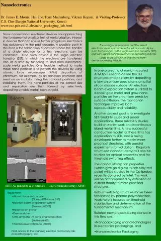
Nanoelectronics • Nanotechnology is the design and construction of useful technological devices whose size is a few billionths of a meter • Nanoscale devices will be built of small assemblies of atoms linked together by bonds to form macro-molecules and nanostructures • Nanoelectronics encompasses nanoscale circuits and devices including (but not limited to) ultra-scaled FETs, quantum SETs, RTDs, spin devices, superlattice arrays, quantum coherent devices, molecular electronic devices, and carbon nanotubes.
Motivation for Nanoelectronics • Limits of Conventional CMOS technology • Device physics scaling • Interconnects Nanoelectronic alternatives? • Negative resistance devices, switches (RTDs, molecular), spin transistors • Single electron transistor (SET) devices and circuits • Quantum cellular automata (QCA) New information processing paradigms • Quantum computing, quantum info processing (QIP) • Sensing and biological interface • Self assembly and biomimetic behavior Issues • Predicted performance improves with decreased dimensions, BUT • Smaller dimensions-increased sensitivity to fluctuations • Manufacturability and reproducibility • Limited demonstration system demonstration
The roadmap Semiconductor technology trends (ITRS 2006)
Materials for Si-nanoelectronics At the origin of Si microelectronics only few elements were necessary for the whole processes. Current technology requires a much larger number of materials. Source: Intel 9
Robert Chau, Intel, ICSICT, 2005 More Moore -> Beyond Moore
Critical issues 4M 104 16M 64M 256M 103 1G 4G 102 16G Memory Capacity/Chip Channel Electrons 101 100 10-1 2020 1988 1992 1996 2000 2004 2008 2012 2016 Year
Nano-Device Structure Evolution Source: Intel
20V; • Normally-off • Schottky contacts Si-NW transistor: outputcharacteristics Lg= 1.3µm; Ø = 26 nm; tox = 300nm SiO2 Id Vd NW S D gate Vg Weber, W.M. et al. IEEE Proc. ESSDERC 2006, p. 423 (2006) 15
gate Photodetector Input nanocrystals Quantum dotsor single electron transistors as processing elements SiO2 source drain gate Memory node Si channel CMOS Drivers providing fan-out SiO2 Single “cell” of a Cellular Architecture 4 1 0 3 2 “1” “0” Possible Quantum Dot Applications Nanoelectronic Integrated Circuit (NIC) Single Electron Memory Quantum Computation (QBITs) Quantum Cellular Automata Quantum dots Quantum dots Tunneling barriers
Beyond Moore Beyond CMOS logic and memory device candidates: • Nanowire transistors • CNT transistors • Resonant tunneling devices • NEMS devices • Single electron transistors • Molecular devices • Spintronic devices All those candidates (some of which not yet demonstrated) still suffer from major reliability and stability problems
Molecular components 20 nm embedded GaAs layer after etching and deposition of 3 nm Ti and 7 nm Au. 5 nm embedded GaAs layer after etching and deposition of 2 nm Ti and 6 nm Au. OPV11 molecules with simplified phenyl side chains synthesized by the group of Prof. Dr. E. Thorn-Csányi at the University of Hamburg) In collaboration with G. Abstreiter, WSI, M. Tornow, TU Braunschweig S. Strobel et al., SMALL 5, 579-582 (2009)
Cross bar non volatile memory A crossbar memory – probably the simplest possible functional circuit – is one of the proposed application of single molecule electronics The current-voltage characteristics of molecules is typically hysteretic, with step-like nonlinearities and possibly non-symmetric (rectifying) behavior. G. Casaba et al., IEEE Transactions on Nanotechnology, 8, 369 (2009)
Problems with single molecule devices A large variation is found in the IV characteristics between succesive sweeps. • Reasons can be due to: • Configurational changes in single • molecules • Variation in the number of • molecules attached to the • electrodes • Changes in the bond of a single • molecule to the metal contact • … Such variability has to be dealt at a circuit/architecture level
Molecular transistor Once a conducting molecule is set between 2 contacts, an additional electrode has be introduced as gate. There are various possibilities: Back gate: a molecule attached to source and drain electrodes on an oxidized metal or heavily doped Si gate (substrate). This is the same configuration of the Thin Film Transistors Electrochemical gate: a molecule bridged between source and drain electrodes in an electrolyte in which a gate field is applied by a third electrode inserted in the electrolyte. Chemical gate: current through the molecule is controlled via a reversible chemical event, such as binding, reaction, doping or complexation.
Coupled nanomagnets Fabrication and pictures by A. Imre Simulation AFM Simulated field Investigations of permalloy nanomagnets (thermally evaporated and patterned by electron beam lithography) confirm the simulation results MFM Courtesy of W. Porod, Notre Dame University
Planar Majority Gate Design • Output points down only if both inputs are pointing up NAND gate. • Difficult to design – ferro- and antiferromagnetic couplings to the central dot should be equally strong • Electrical inputs are difficult to fabricate – horizontally lying dots provide a hard-wired input. No output, we just imaged it with the MFM • Design is based on Parish and Forshaw: Magnetic Cellular Automate Systems IEE Proc.-Circuits Devices Syst., Vol. 151, No. 5, October 2004 Input A Output Programming input (bias to center dot) Input B Imre et. al. Science 2006 3
Working majority gate with nanomagnets MFM images SEM images Imre et. al. Science 2006
Information propagation Inputs Outputs Logic with nanomagnets • The challenges: • How to make signals propagating? Integrated clocking • How to write in the magnets? Localized field from wires • How to read out the magnets? Hall sensor In collaboration with M. Becherer and D. Schmit-Lansiedel (TUM) , W. Porod (Notre Dame) M. Becherer et al., IEEE TRANSACTIONS ON NANOTECHNOLOGY 7, 316 (2008)
More than Moore Interfacing to the real world If the interaction is based on a non-electrical phenomenon, then specific transducers are required. Sensors, actuators, displays, imagers, fluidic or bio-interfaces (DNA, Protein, Lab-On-Chip, Neuron interfaces, etc.) are in this category Enhancing electronics with non-pure electrical devices New devices can be used in RF or analog circuits and signal processing. Thanks to electrical characteristics or transfer functions that are unachievable by regular MOS circuits, it is possible to reach better system performances. RF MEMS electro-acoustic high Q resonators are a good example of this category. Embedding power sources with the electronics: Several new applications will require on-chip or in-package micro power sources (autonomous sensors or circuits with permanent active security monitoring for instance). Energy scavenging micro-sources or micro-batteries are examples of this category.
Why organic electronics ? Easy to process (low costs) Large area application Flexible substrates Chemical tunability of conjugated polymers (absorption spectrum) Easy integration in different devices Ecological and economic advantages Example of organic sheet-image scanner Inkjet-Printed solar cell from Konarka OLED Display For Mp3-player OLED TV from Sony 27
OPD with on/off ratio of more than 104 @ -1 V Organic Photodetectors on glass Bulk heterojunction photodetector ITO/PEDOT:PSS/P3HT:PCBM/LiF/AL 0.6 nm LiF, 100 nm Al 140 nm P3HT:PCBM (1:1) S. Tedde et al., Fully Spray Coated Organic Photodiodes, Nano Letters 9 (3), 980 (2009)
I/V Thin Film Encap. Ag Ca P3HT:PCBM blend PEDOT:PSS Au or ITO Multibarrier PET Foil Organic Photodetectors on plastic In collaboration with Siemens CT MM1
Integration with CMOS • The combination of organic semiconductors with a CMOS-chip offers advantages compared with a conventional CMOS-sensor: • high photosensitivity -> fill factors up to 100 % • wavelength tunability -> sensors for infrared/ultraviolet region • inexpensive fabrication • subwavelength grading for optimized performance and polarization sensitivity Al 100 nm PCBM:P3HT ITO glass-substrate • Requirements for combination CMOS-organic: • work function of the metallization of CMOS chip must be aligned to organic semiconductor energy levels -> e.g. Aluminium • deposition process of organic semiconductors should be possible on rough/patterned surfaces LiF 1nm PEDOT ITO 100 nm Standard organic photodetector In collaboration with Uni. Trento and Fondazione Bruno Kessler 30
Preliminaryresults on invertedstructure • IV-curves (dark/light): • on/off-ratio can be even better than of standard device • lower dark current • lower light current (due to higher absorbance of gold electrode compared with ITO) • higher serial resistance • Transmission of gold-electrode (20 nm) D. Baierl et al., to be published in Organic Electronics 31
Nanotechnology provides a variety of interesting and promising nanostructures Integration with CMOS will be the first step in the profitable use of nanostructures, once process compatibility is proven Critical issues such as reliability, stability and lifetime are going to become routine and will have to be addressed at a circuit/architecture level Novel circuits and architectures are going to be needed for a full exploitation of nanocomponents Conclusions
Teaching activities • Lectures • NANOLECTRONICS (6. Sem. Bach. EI) • NANOSYSTEMS (1. Sem. MSc. EI,) • MOLECULAR ELECTRONICS (2. Sem. MSc. EI) • COMPUTATIONAL METHOD IN NANOELECTRONICS (2. Sem. MSc. EI) • SEMICONDUCTOR QUANTUM DEVICES (1. Sem. MSc. EI) • NANOTECHNOLOGY (1. Sem. MSc. EI, MSc. “Microwave Engineering”, • MSc “Communication Engineering”, MSc. in “Engineering Physics”) • Labs • Nanoelectronics (6. Sem. Bach. EI.) • Simulation of semiconductor nanostructures (MSc. EI) • Characterization and simulation of molecular devices (MSc. EI.) • Design of molecular circuits (MSc. EI) • Nanobioelectronics (MSc. EI)
International Initiatives Joint Bachelor Program in EE with Georgiatech Joint Master Program NTU/TUM on "Integrated Circuit Design„ Joint Master Program NTU/TUM on „Microelectronics„ Int. Master in „Communication Engineering“ (section on „Comunication Electronics“) Int. Master in „Nanoscience and Nanoengineering“ (starting 2011) Joint Ph.D. Program (BI-NATIONALLY SUPERVISED DOCTORAL THESIS) with University of Trento (Italy) Joint Ph.D. Program (BI-NATIONALLY SUPERVISED DOCTORAL THESIS) with Universita‘ delle Marche (Italy) Research cooperations with several european and international companies, research labs and universities (STMicroelectronics, IBM, Arizona State University, MIT, Notre Dame University, University of Illinois U.C., Nanyang Technological University, Universita‘ di Roma „Tor Vergata“, Universita‘ di Modena, …)
Bachelor EI (since Oct. 2008) Menu „Nanoelectronics“ (30 Credits; 5. and 6. Semester) Nanoelectronics 5 Sem 6 Credits CMOS-Technologie 5 Sem 3 Credits Schaltungssimulation 5 Sem 3 Credits Praktikum Elektronische Bauelemente 5 Sem 3 Credits Nanotechnology 6 Sem 6 Credits Halbleitersensoren 6 Sem 3 Credits Optoelektronik 6 Sem 3 Credits Projektpraktikum Nanoelektronik und Nanotechnologie 6 Sem 3 Credits
MS Communication Engineering A paid internship of 10 weeks duration in a German company is intended for the semester break between the 2nd and the 3rd semester.
MS Engineering Physics Among the elective lectures in Material Science students can choose , among others, “Semiconductor Nanoscience and Technology I”, “Bio- and Nanoelectronic Systems I and II”, “Introduction to surface and interface physics”, as special physics lecture, or “Molecular Electronics”, “Nanotechnology”, “Selected Topics in Nanotechnology” as engineering lecture Energy Science: provide a specialized education in Energy Science with lectures ranging from fission, fusion to all kinds of renewable energies. Materials Science: dedicated education in Materials Science including lectures in bio-physics, low dimensional electronic systems, quantum optics, solid state spectroscopy and many more.
International MS Programs in Singapore • A series of Joint International MS Programs are offered by TUM together with NTU : • Microelectronics • Integrated Circuit Design • Aerospace Engineering (from Aug. 2009) • and with NUS • Industrial Chemistry • in Singapore
PCP/SPUR Programme Master Programmes under Professional Conversion Programme (PCP) with SPUR (Skills Programme for Upgrading and Resilience) funding GIST and the Singapore Workforce Development Agency (WDA) are jointly rolling out four Master of Science programmes targeted at Professionals, Managers, Executives, Technicians (PMETs) who would like to convert or upgrade their skills under the Professional Conversion Programme (PCP). This coming May, the Master of Science in Integrated Circuit Design will commence for PMETs who are seeking a career in the Integrated Circuit Design industry. Trainees* need only pay net fees of *S$3210 (inclusive of GST) to get a world class education from leading Universities (NTU and TUM). Programmes which are offered under SPUR funding: Master of Science in Industrial Chemistry TUM / NUS Master of Science in Microelectronics TUM / NTU Master of Science in Integrated Circuit Design TUM / NTU Master of Science in Aerospace Engineering TUM / NTU
MS Nanoscience and Nanoengineering • International MS program in English • Initial selection of candidates • In the first semester, 12 credits will be devoted to the attempt of providing a common background for all. Thus, students with a Bachelor in Physics will be required to take two modules of basics engineering courses (2 in the table) while students with an EI Bachelor will take two basic physics modules (1 in the table). • Modules with 3 ECTS corresponds to a standard course with 2 hours lecture and 1 hour recitation. Modules with larger numbers of credits combine lectures with practical works, seminars or, in some cases, homework.
Nanoelectronics is slowly entering the EE curricula at both Bachelor and MS level Interdepartment and interfaculty curricula are necessary, especially between EE, Physics, Material Science, Chemistry and Biology Very interesting opportunities offered by international cooperations Great potentials for nanoelectronics in the areas of energy, medicine and automation, both for teaching and research Conclusions
MDM U Tor Vergata Acknowledgments Institute for Nanoelectronics nano