Download
1 / 29
290 likes | 311 Vues
Explore the Lower Optical Metering Structure design, planned studies, Coldplate Assembly FEA, and assembly techniques for a telescope focal plane assembly mockup.

E N D
Lower Optics Metering StructureSNAP Collaboration meeting June 2006Robin Lafever LBNL
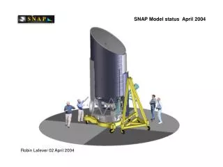
Overview The focal plane assembly is currently being rendered as a full scale physical mockup. The lower Optical Metering Structure is now being designed and will also be rendered in full scale. Planned studies include: Full-scale physical layout and iteration of electronics cabling, thermal straps, through-fittings, and electronics installation on the Instrument deck. Explore critical interfaces at the Focal Plane assembly, Shield assembly, and the Cassegrain shutter before ICDs are formalized. Explore assembly, access, and servicing issues and get a preview of GSE requirements. Develop fab and assembly techniques specific to “egg-crate” construction.
Coldplate Assembly FEA Early FEA modeling set the starting dimensions for the current Coldplate designs FEA: Bobby Besuner
Coldplate Thermal Model Thermal studies confirmed the FEA studies and established starting Dimensions. Actual thermal strap details and mounting scenarios will be worked out on the full-scale mockup Thermal model: Pat Jelinsky
Coldplate Model The current Coldplate conceptual design Is seen as a symetrical grid, Silicon Carbide structure. Nominal thickness ~50mm Cell-to-cell pitch: 46.2mm Detector mount footprint: 31mm X 35mm. A new Coldplate design is in the works. It’s detector footprint is 31mm X 31mm.* Mockups exist with different diameters, 620mm and 680mm, to explore different Shield/Coldplate interfaces.
Coldplate Mockup Full scale Coldplate mockups exist in two diameters. Both have 31mm X 35mm detector footprints. * Current mockups have 46.2mm cell-to-cell pitch. Mockups exist with different diameters, 620 mm and 680 mm, to explore different Shield/Coldplate interface treatments. * Charlie Baltay has shown up at the collaboration meeting with a georgeous Focal Plane Mockup ready for final machining with the 31 mm X 31 mm Detector footprint.
Optical Metering structure modeling Ray trace model Mike Sholl Thermal model Pat Jelinsky Structural FEA model Bobby Besuner CAD model Robin Lafever
Lower optical metering structure Current conceptual design calls for structure to be fabricated from M55J Carbon fiber stock.. “Egg-crate” construction relies on water-jet Profiles cut out of 2mm carbon fiber board and assembled with “tab-and-slot” features And edge bonded joints throughout. A full scale mockup is under way, continuing from the focal plane assembly to the Lower optical metering structure. Upper metering structure and the Instrument deck and radiator will be added later.
Lower optical metering structure Secondary mirror Cassegrain shutter Primary mirror “Ring-of-fire” Assembly Tertiary mirror Shield assembly Fold-flat mirror Focal Plane Lower optical metering structure
Lower optical metering structure Cassegrain shutter “Ring-of-fire” Assembly Tertiary mirror Shield assembly Fold-flat mirror Focal Plane Coldplate Lower optical metering structure
Lower optical metering structure Lower optical metering structure
Lower optical metering structure Focal Plane closeout Tertiary mirror closeout Bellows Assembly
Lower optical metering structure Alternate closeout
Lower optical metering structure Lower optical metering “egg-crate” structure Tertiary closeout Focal Plane Closeout Tertiary mirror Bellows assembly
Lower optical metering structure Lower optical metering “egg-crate” structure Focal Plane Tertiary mirror
Lower optical metering structure Lower optical metering “egg-crate” structure Focal Plane Fold-flat mirror Tertiary mirror
Focal Plane Assembly support structure build-up Attach points for thermal straps The Coldplate mockup currently Has a 46.,2 mm cell-to-cell pitch And a 31 mm X 35 mm detector footprint, Nominal thickness is ~50 mm. The next version will have a 31 mm X 31mm Detector foot print. Both models are ‘universal’ in that they accommodate both TMA-69 and TMA-72 optical prescriptions. Attach points for bipod assemblies
Focal Plane Assembly support structure build-up Bipods are fully kinematic. In this version, final position adjustments are made with shims at the base of each foot.
Focal Plane Assembly support structure build-up Shield/ Ring-of –fire assembly and Shield bipods are shown in the installed position. Mounting details are identical to the Coldplate Mounts.
Focal Plane Assembly support structure build-up Bulkhead installed with ‘5-sided’ boxes in place to receive the Coldplate bipods.
Focal Plane Assembly support structure build-up ‘5-sided boxes’ captured by egg crate webbing.
Focal Plane Assembly support structure build-up ‘5-sided boxes’ captured by egg crate webbing.
Focal Plane Assembly support structure build-up Similar treatment is given to the Shield mounts
Focal Plane Assembly support structure build-up This part of the Lower Optical Metering Structure, including truncated top, bottom, and sides, will be the first structure to be fabbed and will be used as the test stand for the continuation of the Focal Plane mockup. This will be our first shot using the ‘Tab and slot’ assembly technique
Lower optical metering structure Current design is in 2 mm carbon fiber board, waterjet cut, and edge bonded. Cassegrain shutter We plan to make the Mockup with ~3 mm hardboard using waterjet and edge bond fabrication techniques Tertiary closeout Lower optical metering structure Focal Plane closeout Bellows assembly
Cassegrain shutter Focal plane/Shield assembly Tertiary mirror Fold-flat mirror Focal Plane closeout Lower optical metering structure
Cassegrain shutter Focal plane/Shield assembly Tertiary mirror Fold-flat mirror Focal Plane closeout Lower optical metering structure
Future plans Over the next few weeks, we expect to start cabling and thermal strap iterations in full scale on the focal plane mockup. The ‘front end’ section of the Lower optical structure, and a skeleton of the focal plane Closeout will be assembled and integrated with the Focal plane mockup. Cabling will extend to the slice boxes. Crude mockups of the Shield assembly are being studied now and may become stand-ins for a better model at a later date. When a new 31 mm x 31 mm footprint Coldplate is detailed, a new Coldplate mockup will be fabbed, and a call will go out to collaborators for mockups or prototypes of Detector packages and a simple Spectrograph mockup.