Download
1 / 72
720 likes | 837 Vues
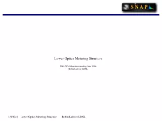
CUORE Clean room Radon abatement Several scenarios exploring the ‘Radon Box’ approach This is an unfinished DRAFT, slammed together for today’s phone meeting !. Robin Lafever LBNL and LNGS. Scenario 1 The generic ‘Radon Box’.

E N D
CUORE Clean room Radon abatementSeveral scenarios exploring the ‘Radon Box’ approachThis is an unfinished DRAFT, slammed together for today’s phone meeting ! Robin Lafever LBNL and LNGS
Scenario 1 The generic ‘Radon Box’ The primary intent for this presentation is to summarize ongoing discussions of the CUORE clean room design with enough detail to give clean room vendors an overview of our requirements. Since Radon abatement is NOT a part of typical clean room construction, this presentation hopefully provides a starting point to evaluate the feasibility and practicality of implementing an integrated Radon-tight/Clean Room installation. Robin Lafever
Scenario 1 The generic ‘Radon Box’ The box concept treats the Radon Barrier and the Clean Room structure as two separate systems. This treatment avoids potential problems of modifying or adapting a conventional Clean Room to also act as a Radon barrier, and isolates their functions. Some assumptions and constraints are: Clean Room construction and assembly will occur after the structural steel work is in place, the external Hut skin is installed, and may overlap with Cryostat assembly and commissioning. All work will be done inside the installed Hut skin, if possible. Radon barrier materials and joint details are not subject to Radon permeability. Barrier materials are selected with assembly techniques in mind. Radon box construction is assumed to be all welded joints, no glued or bonded joint details. Candidate materials include Stainless steel, Galvanized steel, polypropylene, polyethylene, and possibly copolymer Food packaging films, all of which have a practical welding technique appropriate to the material. Material thickness is selected to avoid significant Radon contribution through permeation. Air handling and filtration equipment will utilize the ‘Balcony’ deck, above the Clean Room roof and adjacent to the Faraday cage. All the Clean Room structures and hardware are inside the Radon Barrier. No penetrations through the Radon barrier. All utility penetrations through the Radon barrier are installed with vacuum feed-thru fittings. Radon-Free Air can / will be pumped directly to the critical working area. Robin Lafever
Topics The basic ‘Radon Box” 300 K Flange modifications Timing Scenario 1 Exterior Ductwork Scenario 2 Interior Ductwork Scenario 3 Clean Room Zones Scenario 4 Radon Barrier Zones Doors Robin Lafever
The basic ‘Radon Box” Radon Barrier installed As a single sealed unit, the ‘Radon Box’ This face is transparent to show ductwork connecting the Air-handling Bay to the main Radon Box structure Robin Lafever
The basic ‘Radon Box” The current Clean Room in place Robin Lafever
The basic ‘Radon Box” The current Clean Room in place with the Radon box cut away . In this concept, Clean Room Air handling, ductwork and ceiling filters and floor vents are all installed independently inside the Radon Box Robin Lafever
The basic ‘Radon Box” Default Clean Room installed. Supply air goes into the ceiling and return air goes through the floor, back to the equipment Bay on the ‘Balcony’. Robin Lafever
The basic ‘Radon Box” The Radon Box is a single continuous skin (with the exception of the 300 K Flange area and shield access hole in the floor) Note that columns are outside the Radon Barrier. The interior is isolated from Radon emanation from the steel building structure, and vibration isolation from the cryostat support columns is no longer needed. Robin Lafever
The basic ‘Radon Box” There is some limit on where exterior ductwork can be placed. This configuration shows the duct between the CUORE hut and The CRESST building. Robin Lafever
The basic ‘Radon Box” The ducts could be expanded into a plenum under the floor, however, this is a busy area, with utilities, lighting, and a Crane system on the ceiling of the lower floor. Robin Lafever
The basic ‘Radon Box” Robin Lafever
The basic ‘Radon Box” Robin Lafever
The basic ‘Radon Box” Robin Lafever
The basic ‘Radon Box” Robin Lafever
Timing Robin Lafever
Timing Robin Lafever
Timing Robin Lafever
Timing Robin Lafever
Timing Robin Lafever
300 K Flange modifications Robin Lafever
300 K Flange, MODIFIED In addition, feed-through assemblies are required for the Lifting assembly. The radial position and feed-through details are not known at the moment, but this treatment shows Radon Seals and cables inside the adapter flange. Robin Lafever
300 K Flange, MODIFIED Bottom view Note that the Suspension assemblies Are potential Radon leaks and need seals. The details are not known to me, however, I Show an assembly that could incorporate O-ring packing glands. Robin Lafever
Top section view showing Suspension hardware, Cable feed-throughs, and the adapter Flange with Radon Barrier/vibration isolator Note that the feed-through will need some radial space, TBD. Robin Lafever
Bottom section Again, note that the suspension Hardware needs a Radon seal Again, this is a potential Radon leak And will need some kind of seal. I do not know what the actual details are. Robin Lafever
300 K Flange modifications Robin Lafever
300 K Flange modifications Robin Lafever
300 K Flange modifications Robin Lafever
300 K Flange modifications Robin Lafever
300 K Flange modifications Robin Lafever
Scenario 2 Internal Ductwork Robin Lafever
Scenario 2 Internal Ductwork Robin Lafever
Scenario 2 Internal Ductwork Robin Lafever
Scenario 2 Internal Ductwork Robin Lafever
Scenario 2 Internal Ductwork Robin Lafever
Scenario 2 Internal Ductwork Robin Lafever
Scenario 2 Internal Ductwork Robin Lafever
Scenario 3 Clean Room Zones Robin Lafever
Scenario 3 Clean Room Zones Robin Lafever
Scenario 3 Clean Room Zones Robin Lafever
Scenario 3 Clean Room Zones Robin Lafever
Scenario 2 Internal Ductwork Robin Lafever
Scenario 2 Internal Ductwork Robin Lafever
Scenario 4 Radon Barrier Zones Robin Lafever
Scenario 4 Radon Barrier Zones Robin Lafever