Download
1 / 65
650 likes | 859 Vues
Chapter 3 HCS12 Members and Hardware and Software Development Tools. The HCS12 Members (1 of 2). Is a redesign of the 68HC12 family The 68HC12 family is an upgrade of the popular 68HC11 8-bit microcontroller family. The 68HC12 has a highest bus clock frequency of 8 MHz.

E N D
Chapter 3HCS12 Members and Hardware and Software Development Tools
The HCS12 Members (1 of 2) • Is a redesign of the 68HC12 family • The 68HC12 family is an upgrade of the popular 68HC11 8-bit microcontroller family. • The 68HC12 has a highest bus clock frequency of 8 MHz. • The HCS12 family has a highest bus clock frequency of 32 MHz. • The numbering system is shown in Figure 3.1. -
- The HCS12 Members (2 of 2) • The HCS12 was initially designed for automotive and process control market. • The HCS12 has many features designed for these target markets: • Parallel ports • Timer functions: input capture, output compare, pulse accumulation, real-time interrupt, pulse width modulation, modulus down counter • Serial communication interface (SCI) • Serial peripheral interface (SPI) • Inter-integrated circuit (I2C) • Byte data link control (BDLC) • Controller Area Network (CAN) • Freescale also included the background debug mode (BDM) in each HCS12 member to facilitate the software debugging activities. • Freescale also include special features to target other applications: • Ethernet controller: the MC9S12NE64 has an Ethernet controller to facilitate the access of the Internet. • USB controller: the MC9S12UF32 has an on-chip USB controller to facilitate the interfacing with USB bus.
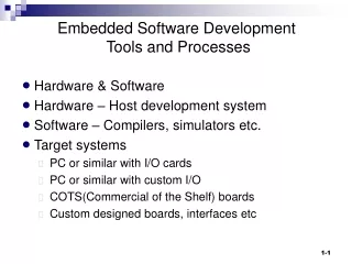
Development Tools • Software development tools • Text editor, terminal program, cross assembler, cross compiler, simulator, source-level debugger, integrated development environment (IDE) • Hardware development tools • Oscilloscope, function generator, in-circuit emulator, logic analyzer, demo board • Only demo boards and BDM kit will be discussed.
Software Development Tools • A text editor allows the user to enter and edit the program. • A cross assembler allows the user to assemble their assembly programs. • A cross compiler allows the user to compile their programs written in high-level languages. • A simulator allows the user to run the application program without having the actual hardware. • A terminal program allows the PC to communicate with the hardware demo board. • A source-level debugger allows the user to set breakpoints in the program, trace program execution, watch program variable values after program execution, and so on. • An IDE combines all of the above programs in one package so the user can perform all software debugging activities in one environment without quitting any program. • The freeware miniIDE and asmIDE are recommended for assembly program development. • The freeware EmbeddedGNU IDE and GNU C compiler are recommended for C program development.
Demo Boards • Many HCS12-based demo boards are available for learning the HCS12 and debugging the HCS12 application programs. • A demo board has an HCS12 MCU and many peripheral chips to help test the HCS12 programs. • A demo board often has an on-board monitor program to communicate with a PC or workstation on which the user develops the application program. • The monitor program allows the user to display register and memory location contents, setting register and memory location contents, setting program breakpoints, tracing instruction execution, and download programs onto the demo board for execution. • The PC or workstation communicates with the demo board using the terminal program. • The SSE256 from Shuan Shizu and the Dragon12 from Wytec are recommended for learning the HCS12 microcontroller.
24-MHz bus speed (generated from a 4-MHz crystal) D-Bug12 monitor 16 x 2 LCD kit (4-bit interface) Eight LEDs Four seven-segment displays Keypad connector Four buttons for input DIP switches for input Buzzer for playing siren and songs (wired to the PT5 pin) Potentiometer for testing A/D function (wired to PAD7 pin) Infrared transceiver CAN transceiver (Philips PCA82C250) A small breadboard BDM IN and BDM OUT connectors Two RS232 connectors LTC1661 10-bit D/A converter chip with SPI interface 24LC16 serial EEPROM with I2C interface Additional information is available at www.evbplus.com The Dragon12 Demo Board (1 of 2)
24-MHz bus speed (generated from a 16-MHz oscillator) D-Bug12 monitor 20 x 2 LCD kit (8-bit interface) Eight LEDs Four seven-segment displays Function generator with square waveform output, 24 frequency outputs ranging from 1 Hz up to 16 MHz (half of the them are in power of 2) DIP switches for data input Keypad connector Four debounced switches for input with interrupt capability DS1307 real-time clock chip with I2C interface 24LC08 serial EEPROM with I2C interface TC72 digital thermometer with SPI interface TLV5616 12-bit D/A converter with SPI interface Buzzer for playing siren and songs (can be driven by any output input) Potentiometer for testing A/D function (wired to the PAD7 pin) CAN transceiver (MCP2551) BDM IN and BDM OUT connectors Two RS232 connectors Additional information available at www.evb.com.tw The SSE256 Demo Board (1 of 2)
The D-Bug12 Monitor • Supports most HCS12 devices with 128KB and 256 KB flash memory • Used in many demo boards • Requires a host terminal program that supports the Xon/Xoff software handshake for proper operation • The HyperTerminal bundled with Windows and the terminal program bundled with asmIDE, miniIDE, and EmbeddedGNU IDE can work with D-Bug12 monitor. • Supports four operating modes: EVB mode, Jump to EEPROM mode, POD mode, and Serial Bootloader mode • After reset, the D-Bug12 reads the logic levels on the PAD1 and PAD0 pins to decide which of the four D-Bug12 modes to enter.
- EVB Mode • The D-Bug12 monitor operates from the flash memory • The users are restricted to use SRAM (from $1000 to $3BFF) or EEPROM to run application programs. • The user runs a terminal program on the PC to communicate with the D-Bug12 monitor on the demo board. • EVB operation model is shown below. When the demo board is powered up and the baud rate is set properly, the message as shown to the right will appear on the terminal screen.
The D-Bug12 monitor displays the “>” character to indicate it is ready for operation. • When a command issued to D-Bug12 is successfully executed, the monitor displays the execution result and a new > character on a new line. • If a command is not successfully executed, press the reset button to get out. • An alternative to get out of the unsuccessful command is to press the abort key. • The abort key is connected to the XIRQ signal. • Both the SSE256 and Dragon12 demo boards use the MC9S12DP256 as their MCU. • The memory maps for these two demo boards are shown below.
Using the MiniIDE (1 of 18) • Step 1. Invoke the MiniIDE by double clicking the icon of MiniIDE. • Step 2. Communicating with the demo board • Press the Terminal menu (shown in Figure C.2) and select Show Terminal Window. • Press the reset button on the demo board and the screen will change to Figure C.3.
Using the MiniIDE (4 of 18) • Step 3. Setting options • - Set Options can be found under the Build menu and Terminal menu.
Using the MiniIDE (6 of 18) • Options in General category
Using the MiniIDE (7 of 18) • Options in Terminal category
Using the MiniIDE (8 of 18) • Options in Tool category
Using the MiniIDE (9 of 18) • Options in Assembler category
Using the MiniIDE (10 of 18) • Step 4. Open a new file for entering an assembler program. • Press the File menu and select New and the screen is changed to Figure C.10. • Enter the program as shown in Figure C.11. • Save the file after the whole program is entered. Press the File menu and select Save as shown.
Using the MiniIDE (13 of 18) • Step 5. Assemble the program. • Press the Build menu and select Build siren.asm as shown. • After a successful assembly, the status window will display the corresponding message as shown.
Using the MiniIDE (15 of 18) • Step 6. Download the program onto the demo board. • Type the load command followed by the enter keyin the terminal window. • Press the Terminal menu and select Download File (shown in Figure C.15). • A dialog box as shown in Figure C.16 appears. • Enter the name of the file to be downloaded and click on Open. • After a successful download, the screen is changed to Figure C.17.
Using the MiniIDE (18 of 18) • Step 7. Running and debugging the program • Type g 2000 followed by enter key. • This program will generate a two-tone siren.
Using the D-Bug12 Commands • - BF <StartAddress> <EndAddress> [<Data>] • Fill a block of memory locations with the value of <Data>. • To fill the memory locations from $1000 to $1FFF with 0, enter the following command: • >bf 1000 1FFF 0 • - MD <StartAddress> [< EndAddress >] • Display memory contentsfrom < StartAddress > to < EndAddress >. • 16 bytes are displayed on each line. • The <StartAddress> is rounded down to the next lower multiple of 16. • The <EndAddress> is rounded up to the next higher multiple of 16. • Only one line is displayed if the EndAddress is not specified.
>md 1000 1000 AA 85 06 0C - D7 98 9A 61 - DF BE BC E9 - 03 AE D0 3D .......a.......= >md 1005 1020 1000 AA 85 06 0C - D7 98 9A 61 - DF BE BC E9 - 03 AE D0 3D .......a.......= 1010 75 DA DF 39 - 3F 34 BD A9 - 2A CA FA DB - AC DA 18 97 u..9?4..*....... 1020 4D 5B 48 BA - B2 F7 B6 1B - 92 99 E5 E4 - A5 E9 01 9F M[H............. > MDW <StartAddress> [<EndAddress>] >mdw 1000 1000 AA85 060C - D798 9A61 - DFBE BCE9 - 03AE D03D .......a.......= >mdw 1000 1020 1000 AA85 060C - D798 9A61 - DFBE BCE9 - 03AE D03D .......a.......= 1010 75DA DF39 - 3F34 BDA9 - 2ACA FADB - ACDA 1897 u..9?4..*....... 1020 4D5B 48BA - B2F7 B61B - 9299 E5E4 - A5E9 019F M[H............. >
MM <Address> [<Data>] • Used to examine and modify the contents of memory locations one byte at a time. • If the 8-bit data parameter is present on the command line, the byte at memory location • <Address> is replaced with <Data> and the command is terminated. • If no data is provided, then D-Bug12 enters the interactive memory modify mode. • In the interactive mode, each byte is displayed on a separate line following the address of data. • Single-character sub-commands are used for the modification and verification of memory contents in interactive mode. • The available sub-commands are as follows: [<Data>] <CR> Optionally update current location and display the next location. [<Data>] </> or <=> Optionally update current location and redisplay the same location. [<Data>] <^> or <-> Optionally update current location and display the previous location. [<Data>] <.> Optionally update current location and exit Memory Modify.
>mm 1000 1000 00 1001 00 FF 1002 00 ^ 1001 FF 1002 00 1003 00 55 / 1003 55 . > MMW <Address> [<Data>] - Allows the contents of memory to be examined and/or modified as 16-bit hex data. - If the 16-bit data is present on the command line, the word at memory location <Address> is replaced with <Data> and the command is terminated. - If no data is provided, then D-Bug12 enters the interactive memory modify mode. - MMW supports the same set of sub-commands as does the MM command.
>mmw 1100 1100 00F0 1102 AA55 0008 1104 0000 ^ 1102 0008 aabb 1104 0000 1106 0000 . > Move <StartAddress> <EndAddress> <DestAddress> - The number of bytes moved is one more than <EndAddress> - <StartAddress> >move 1000 10ff 1100 > RD – register display >rd PP PC SP X Y D = A:B CCR = SXHI NZVC 38 1521 3C00 2014 0000 6E:14 1001 0100 xx:1521 9C42 CPD $0042 >
RM – register modification >rm PC=0000 1500 SP=0A00 IX=0000 0100 IY=0000 A=00 B=00 ff CCR=90 d1 PC=1500 . > <RegisterName> <RegisterValue> - Allow one to change the value of any CPU register. - Each bit of the CCR register can be changed by specifying its name.
>pc 2000 PC SP X Y D = A:B CCR = SXHI NZVC 2000 0A00 0100 0000 00:FF 1101 0001 >x 800 PC SP X Y D = A:B CCR = SXHI NZVC 2000 0A00 0800 0000 00:FF 1101 0001 >c 0 PC SP X Y D = A:B CCR = SXHI NZVC 2000 0A00 0800 0000 00:FF 1101 0000 >z 1 PC SP X Y D = A:B CCR = SXHI NZVC 2000 0A00 0800 0000 00:FF 1101 0100 >d 2010 PC SP X Y D = A:B CCR = SXHI NZVC 2000 0A00 0800 0000 20:10 1101 0100 >
ASM <Address> (1 of 2) • Invokes the one-line assembler/disassembler. • Allows memory contents to be viewed and altered using assembly language mnemonics. • When displaying instructions, each instruction is displayed in its mnemonic form. • The assembly/disassembly process can be terminated by a period. • The one-line assembler displays the current instruction and allows the user to enter new instruction. • User can skip the current instruction by pressing the Enter key.
ASM <Address> (2 of 2) The following example displays instruction starting from $2000: >asm 2000 2000 FC0800 LDD $0800 > 2003 CD0900 LDY #$0900 > 2006 CE000A LDX #$000A > 2009 1810 IDIV > 200B CB30 ADDB #$30 > 200D 6B44 STAB 4,Y > 200F B7C5 XGDX > 2011 CE000A LDX #$000A >. > The following example enters three instructions (in bold face) starting from $1500: >asm 1500 1500 FC0800 LDD $0800 1503 F30802 ADDD $0802 1506 7C0900 STD $0900 1509 E78C TST 12,SP >. >
BR [<Address> …] Setting or Examine Breakpoints • A breakpoint halts the program execution when the CPU reaches the breakpoint address. • When a breakpoint is encountered, the D-Bug12 monitor displays the contents of CPU registers and the instruction at the breakpoint (not executed yet). • Breakpoints are set by typing the breakpoint command followed by one or more breakpoint addresses. • Entering the breakpoint command without any breakpoint addresses will display all the currently set breakpoints. • A maximum of ten user breakpoints may be set at one time. >br 1020 1040 1050 ; set three breakpoints Breakpoints: 1020 1040 1050 >br ; display current breakpoints Breakpoints: 1020 1040 1050 >
NOBR [<Address> <Address>] • Delete one or more previously defined breakpoints. • All breakpoints will be deleted if no addresses are specified. >br 2000 2010 2020 2040 2090 ; set four breakpoints Breakpoints: 2000 2010 2020 2040 2090 >nobr 2000 2010 ; delete two breakpoints Breakpoints: 2020 2040 2090 >nobr ; delete all breakpoints All Breakpoints Removed >
G [<Address>] • Begin execution of user code at the specified address. • If no address is specified, CPU starts execution of the instruction at the current PC address. >g 1500 User Bkpt Encountered PP PC SP X Y D = A:B CCR = SXHI NZVC 38 150C 3C00 7B48 0000 03:E8 1001 0001 xx:150C 911E CMPA $001E >
GT <Address> • Execute instruction until the given address and stop. • User usually needs to specify where the program execution should start before issuing this command. >pc 1500 PP PC SP X Y D = A:B CCR = SXHI NZVC 38 1500 3C00 1000 1002 00:00 1001 0101 xx:1500 CF1500 LDS #$1500 >gt 1540 Temporary Breakpoint Encountered PP PC SP X Y D = A:B CCR = SXHI NZVC 38 1510 1500 1000 1002 1E:00 1001 0000 xx:1510 3B PSHD >
T [<count>] • Used to execute one or multiple instructions starting from the current PC address. • As each program instruction is executed, the CPU register contents and the next instruction to be executed are displayed. • Only one instruction will be executed when no count is specified. >pc 1500 PP PC SP X Y D = A:B CCR = SXHI NZVC 38 1500 1500 1000 1002 1E:00 1001 0000 xx:1500 CF1500 LDS #$1500 >t PP PC SP X Y D = A:B CCR = SXHI NZVC 38 1503 1500 1000 1002 1E:00 1001 0000 xx:1503 CE1000 LDX #$1000 >t 2 PP PC SP X Y D = A:B CCR = SXHI NZVC 38 1506 1500 1000 1002 1E:00 1001 0000 xx:1506 34 PSHX PP PC SP X Y D = A:B CCR = SXHI NZVC 38 1507 14FE 1000 1002 1E:00 1001 0000 xx:1507 861E LDAA #$1E >
CALL [<Address>] • Used to execute a subroutine and returns to the D-Bug12 monitor program. • All CPU registers contain the values at the time the final RTS instruction was executed, with the exception of the program counter. • The program counter contains the starting address of the subroutine when returning from the subroutine. >call 1600 Subroutine Call Returned pp PC SP X Y D = A:B CCR = SXHI NZVC 38 1600 0A00 0032 0900 00:31 1001 0000 xx:1600 FC1000 LDD $1000 >
The Pod Mode • This mode is intended to run the demo board as a BDM host to control a target board. • Arrangement shown below
The Jump-to-EEPROM Mode • Execute a small program from the on-chip EEPROM whenever the EVB is powered up or reset. • This mode provides a way to execute a program in a standalone manner without having to erase and program the on-chip flash memory using the bootloader.
The Bootloader Mode • The Bootloader resides from $F000 to $FFFF. • Bootloader can be used to erase and reprogram the remainder of on-chip flash memory or erase the on-chip EEPROM. • Bootloader utilizes the SCI port for communication. • The only required host program is a terminal program that can communicate at 9600 to 115,200 baud and supports XON/XOFF handshaking. • The bootloader mode prompt is as follows:
Tips for Assembly Program Debugging • Syntax errors • Misspelling of instruction mnemonics • Starting instruction mnemonic at column 1. The mnemonic is treated as a label whereas the operands are treated as mnemonic. • Missing operands • Will be highlighted by the assembler and are easy to fix. • Logic errors • Using extended (or direct) mode instead of immediate mode • A program with this type of addressing mode error is on the next page.