PLC Operation and Programming Guide
230 likes | 541 Vues
Learn about PLC modes of operation, programming methods, memory, and logic gates. Understand how to program a PLC using relay ladder logic for automation control.

PLC Operation and Programming Guide
E N D
Presentation Transcript
RLL: Relay Ladder Logic CONTENTS 1. PLC operation 2. PLC programming 3. Ladder logic 4. Memory and gates
PLC operation A PLC has 2 modes of operation Programming mode: translate engineering language (control logic) to machine language (binary code) Running (or scanning) mode: Relating the program to inputs and outputs
Programming through standard computer Most PLC manufacturers offer software packages that allow a standard computer to be used as a programming terminal
PLC running or scanning mode Relating the program to inputs and outputs The CPU reads the data from the inputs The program in the CPU uses the inputs to evaluate the control logic. As the program runs, the CPU updates the data The CPU writes the data to the output
PLC programming One of the advantages of PLC is that it can be programmed by non-specialists Program can be written in the form of a relay ladder diagram represented in terms of contacts and coils. Contact: A simple input switch. Coil: An output load, e.g., a relay or motor. current Switch/contact coil
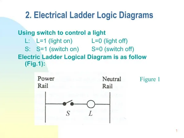
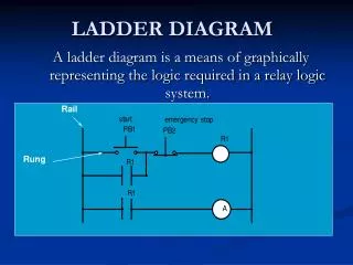
Ladder logic • Power supply rails drawn as parallel vertical lines on left and right • Connection of rails implies current will flow • An output is “on” when a connection is completed and current flows through the load’s coil current Switch/contact coil
Illustration of ladder logic Power circuit Control circuit Switch Relay Coil Simple control circuit of a bell Associated Relay Ladder
Ladder logic: basic notations • Simple “always on” load: [Always_On = 1] note: sometimes illegal • Load controlled by a single contact: [Switch_Con = Switch]
Ladder logic: AND gate, OR gate • Boolean logic C = A and B also noted C = A.B C = A or B also noted C = A+B
Ladder logic: NOT gate • C = (not A) also noted Ā • A contact with a slash through it is “normally closed.” • This indicates a connection when A is NOT triggered. • So when sensor/input A is activated, there is an open circuit
Ladder logic: basic operations • Each rung of the ladder is a statement that is asynchronous when implemented in relay logic, but evaluated sequentially by the PLC. • X = (A+B).(C+D), Y = Ā.[B+(C.D)]
Ladder logic: examples Lamp = SW1 + SW2
Motor starter Ladder logic: setting a memory S1 S1 Q1.1 Q1.1 S1 Relay Coil “R1” Motor 1 Current flow (Scan 1) 2 Current flow (Scan 1) Q1.1 Q1.1 Q1.1 Output Current flow (Scan 2) Current flow (Scan 2) PLC 3 Input Switch “S1” to start 14
Setting memory elements using AND and OR gates S1 R1 S2 S1 R1 S2 Memory Unit AND Gate for setting S3 S3 Memory Unit OR Gate for setting R1 R1 15
Motor starter Ladder logic: resetting a memory Q1.1 S1 Q1.1 S1 Q1.1 S1 Relay Coil “R1” Motor 1 S2 S2 S2 2 Q1.1 Q1.1 Q1.1 Output PLC 3 Input Switches “S1” to start “S2” to stop 16
Resetting memory elements using AND and OR gates S1 R1 S3 S2 R1 The only case for current ON is when (S2 is NOT switched ON) AND (S3 is NOT switched ON) 17
Resetting memory elements using AND and OR gates S1 R1 S2 S3 R1 The only case for current OFF is when (S2 is switched ON) AND (S3 is switched ON) 18
Ladder logic: adding indicators as outputs S1 R1 R1 R1 S2 R1 Q1.1 G R