Turning Operations
Turning Operations. L a t h e. Turning Operations. Machine Tool – LATHE Job (workpiece) – rotary motion Tool – linear motions “ Mother of Machine Tools “ Cylindrical and flat surfaces. Some Typical Lathe Jobs. Turning/Drilling/Grooving/ Threading/Knurling/Facing. The Lathe. The Lathe.


Turning Operations
E N D
Presentation Transcript
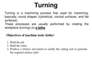
Turning Operations L a t h e
Turning Operations • Machine Tool – LATHE • Job (workpiece) – rotary motion • Tool – linear motions • “Mother of Machine Tools “ • Cylindrical and flat surfaces
Some Typical Lathe Jobs Turning/Drilling/Grooving/ Threading/Knurling/Facing...
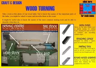
The Lathe Head Stock Tail Stock Bed Carriage Feed/Lead Screw
Main Parts • Bed • Headstock • Feed and lead screws • Carriage • Tailstock
Lathe Bed • Heavy, rugged casting • Made to support working parts of lathe • On top section are machined ways • Guide and align major parts of lathe
Headstock • Clamped on left-hand end of bed • Headstock spindle • Hollow cylindrical shaft supported by bearings • Provides drive through gears to work-holding devices • Live center, faceplate, or chuck fitted to spindle nose to hold and drive work • Driven by stepped pulley or transmission gears • Feed reverse lever • Reverses rotation of feed rod and lead screw
Headstock Back Gear arrangement Headstock belt drive
Quick-Change Gearbox • Contains number of different-size gears • Provides feed rod and lead-screw with various speeds for turning and thread-cutting operations • Feed rod advances carriage when automatic feed lever engaged • Lead screw advances the carriage for thread-cutting operations when split-nut lever engaged
Carriage • Used to move cutting tool along lathe bed • Consists of three main parts • Saddle • H-shaped casting mounted on top of lathe ways, provides means of mounting cross-slide and apron • Cross-slide • Apron
Carriage < Saddle < Apron
Apron • The apron attached to the front of the carriage, holds most of the control levers. These include the levers, which engage and reverse the feed lengthwise (Z-axis) or crosswise (X-axis) and the lever which engages the threading gears. • The apron is fastened to the saddle, houses the gears and mechanisms required to move the carriage and cross-slide automatically. • The apron hand wheel can be turned manually to move the carriage along the Lathe bed. This hand wheel is connected to a gear that meshes in a rack fastened to the Lathe bed. • The automatic feed lever engages a clutch that provides the automatic feed to the carriage
Cross-slide • Mounted on top of saddle • Provides manual or automatic cross movement for cutting tool • Compound rest (fitted on top of cross-slide) • Used to support cutting tool • Swiveled to any angle for taper-turning • Has graduated collar that ensure accurate cutting-tool settings (.001 in.) (also cross-slide)
Top Slide (Compound slide) • Fitted to top of Cross slide • Carries tool post and cutting tool • Can rotate to any angle • Is used to turn tapers
Tailstock • Upper and lower tailstock castings • Adjusted for taper or parallel turning by two screws set in base • Tailstock clamp locks tailstock in any position along bed of lathe • Tailstock spindle has internal taper to receive dead center • Provides support for right-hand end of work
Tailstock Supports long workpieces when machining. Drill Chuck 60 degree rotating center point. Turn the tailstock handwheel to advance the ram.
Lead Screw and Feed Rod < Lead Screw < Feed Rod
Types of Lathes • Engine Lathe • Speed Lathe • Bench Lathe • Tool Room Lathe • Special Purpose Lathe • Gap Bed Lathe …
Size of Lathe Swing Workpiece Length
Size of Lathe .. Example: 300 - 1500 Lathe • Maximum Diameter of Workpiece that can be machined = SWING (= 300 mm) • Maximum Length of Workpiece that can be held between Centers (=1500 mm)
WorkholdingDevices • Equipment used to hold • Workpiece – fixtures • Tool - jigs Securely HOLD or Support while machining
Workholding Devices .. Chucks Three jaw Four Jaw
Chucks • Used extensively for holding work for lathe machining operations • Work large or unusual shape • Most commonly used lathe chucks • Three-jaw universal • Four-jaw independent • Collet chuck
Three-jaw Universal Chuck • Holds round and hexagonal work • Grasps work quickly and accurate within few thousandths/inch • Three jaws move simultaneously whenadjusted by chuck wrench • Caused by scroll plate into which all three jaws fit • Two sets of jaw: outside chucking and inside chucking
Four-Jaw Independent Chuck • Used to hold round, square, hexagonal, and irregularly shaped workpieces • Has four jaws • Each can be adjusted independently by chuck wrench • Jaws can be reversed to hold work by inside diameter
Four-Jaw Independent Chucks • With the four jaw chuck, each jaw can be adjusted independently by rotation of the radially mounted threaded screws. • Although accurate mounting of a workpiece can be time consuming, a four-jaw chuck is often necessary for non-cylindrical workpieces.
Workholding Devices .. Mandrels Workpiece (job) with a hole
Mandrels • Holds internally machined workpiece between centers so further machining operations are concentric with bore • Several types, but most common • Plain mandrel • Expanding mandrel • Gang mandrel • Stub mandrel
Mandrels to Hold Workpieces for Turning Figure 23.8 Various types of mandrels to hold workpieces for turning. These mandrels usually are mounted between centers on a lathe. Note that in (a), both the cylindrical and the end faces of the workpiece can be machined, whereas in (b) and (c), only the cylindrical surfaces can be machined.
Workholding Devices .. Rests Steady Rest Follower Rest
Steadyrest • Used to support long work held in chuck or between lathe centers • Prevent springing • Located on and aligned by ways of the lathe • Positioned at any point along lathe bed • Three jaws tipped with plastic, bronze or rollers may be adjusted to support any work diameter with steadyrest capacity
Follower Rest • Mounted on saddle • Travels with carriage to prevent work from springing up and away from cutting tool • Cutting tool generally positioned just ahead of follower rest • Provide smooth bearing surface for two jaws of follower rest
Operating/Cutting Conditions • Cutting Speed v • Feed f • Depth of Cut d
Operating Conditions.. Cutting Speed D – Diameter (mm) N – Revolutions per Minute (rpm) The Peripheral Speed of Workpiece past the Cutting Tool =Cutting Speed
Operating Conditions.. Feed f – the distance the tool advances for every rotation of workpiece (mm/rev)