ECS Cabin Air Distribution Model for Multi-Mission Aircraft
This presentation discusses the optimization of the ECS cabin air distribution for passengers' comfort and smoke detection in multi-mission aircraft. It highlights the use of CFD analysis to identify improvements and achieve design goals.

ECS Cabin Air Distribution Model for Multi-Mission Aircraft
E N D
Presentation Transcript
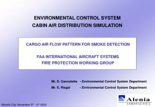
…background • ECS cabin air distribution design for multi-mission aircraft • Air pattern definition is a key factor for ECS design goals • Passengers aircraft and cargo aircraft design objectives usually different (comfort for passengers and prompt smoke detection for cargo configuration) • CFD approach • Tool complexity balanced by powerful investigation capabilities • Technical risks reduction and shorten development phase
Presentation Summary • ECS Cabin Air Distribution Model • Model Creation • Model Development • CFD analysis and improvements identification • Optimization process through iterative loop • CAD-CFD FEM interaction • Model Validation • Design evolution • Full scale aircraft fuselage compartment ground smoke tests campaign • Test results and conclusions
Model Creation and Development • ECS cabin air distribution optimization for passengers comfort and smoke detection • 3D model analyzed by a finite elements method CFD code • Domain extension and computational workload taken into account: • Only a fuselage half section represented • Entire extension obtained through cyclic and symmetrical boundary conditions Symmetric Boundary Condition Cyclic Boundary Condition
First Solution for Cabin Air Distribution - Outlet Inlet Boundary Condition Pressure Boundary Condition Honeycomb Slice Detail
Symmetric Boundary Condition Inlet Boundary Condition Cyclic Boundary Condition Pressure Boundary Condition First Solution for Cabin Air Distribution - Flow Pattern Analysis Cruise at 5000 ft cabin altitude ECS in heating and cooling operations
First Solution for Cabin Air Distribution - Flow Pattern Results Heating Operation (Tf = 167°F, OAT=-67°F) Section at the ECS Outlet
First Solution for Cabin Air Distribution - Flow Pattern Results cont’d Heating Operation (Tf = 167°F, OAT=-67°F) Middle Section between two ECS Outlets
First Solution Analysis Results Shortfalls identified • High air velocity in the cabin and flow pattern jeopardizing smoke detection • Passengers comfort penalties Corrective action • New design of the ECS outlet, changing the orientation on the surface fuselage
Final Solution for Cabin Air Distribution - Outlet Inlet Boundary Condition Pressure Boundary Condition Honeycomb Slice Detail
Final Solution for Cabin Air Distribution - Flow Pattern Results Heating Operation (Tf = 167°F, OAT=-67°F) Section at the ECS Outlet
Final Solution for Cabin Air Distribution - Flow Pattern Results cont’d Heating Operation (Tf = 167°F, OAT=-67°F) Middle Section between two ECS Outlets
Analysis Results and Design Progress • Air distribution and temperature uniformity with low air velocity in the cabin leading to passenger comfort and smoke detection benefits • the flow pattern in the cabin helps the smoke to rise up to the fuselage ceiling where the smoke detectors are installed • Most suitable zone for the smoke detectors installation identified • the section between two ECS outlets • on the ceiling just after the wall • Analysis results application • CFD Model Validation • Solution embodied into design
x Diffuser ECS Outlet Exit z C ‘ 1.23 in” B’ A’ MID C 23 in” B A 4.92” O y CFD Model Validation Test CFD model validated by test laboratories Measurement, through an anemometer, of the air velocity in different points along two different stations Dedicated CFD model created to simulate the test condition and measurement pattern ECS Outlet Exit Measurement Grid
Ground Smoke Tests Ground smoke tests campaign Compartment full scale mock-up with draw-thru smoke detectors and approved smoke generator ECS outlets and outlets grids detail level reproduced 11 test points along the compartment Different flow conditions in normal operation and failure cases Test Rig Scheme Test Rig Detail Level
Ground Smoke Tests Results Cargo Main Deck - Normal Operation - 25 SCFM - Left Side
Ground Smoke Tests Results Cargo Main Deck - Normal Operation - 32.5 SCFM - Central Zone
Ground Smoke Tests Results Cargo Main Deck - Failure Case - 25 SCFM - Right Side
Conclusions CFD analysis benefits along the design process • Flow pattern simulation compliant with the test results in all the normal operation and failure conditions • Correct identification of the most suitable zone for smoke detectors installation • Flexible investigation on wide spectrum of solutions • Reduction of the smoke detection time • Reduction of the technical risk associated to the development and certification tests