ISAS
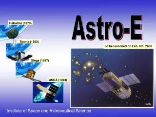
ISAS. Astro-E. Hakucho (1979). Tenma (1983). to be launched on Feb. 8th, 2000. Ginga (1987). ASCA (1993). Institute of Space and Astronautical Science. 5.4 m. 6.5 m. Total Weight 1670 kg.

ISAS
E N D
Presentation Transcript
ISAS Astro-E Hakucho (1979) Tenma (1983) to be launched on Feb. 8th, 2000 Ginga (1987) ASCA (1993) Institute of Space and Astronautical Science
5.4 m 6.5 m Total Weight 1670 kg The Astro-E mission is the fifth in a series of Japanese X-ray astronomy missions, following the Hakucho, Tenma, Ginga and ASCA satellites. It is scheduled to be launched on Feb. 8th 2000 by the M-V launch vehicle from Kagoshima Space Center (KSC), Japan. Astro-E features excellent sensitivity, with high throughput over an unprecedented wide energy band from 0.5 keV to 600 keV. This wide bandpass, combined with high resolution spectroscopic capabilities, makes Astro-E a unique tool capable of addressing a wide variety of fundamental subjects in astrophysics, involving the origins of elements and structures in the Universe as well as the evolution and dynamics of these structures. Astro-E
Development of Astro-E Astro-E was developed at Japan’s Institute of Space and Astronautical Science (ISAS) in an extensive collaboration between scientists from Japan and the United States. • International Collaborations • X-ray Telescope (XRT) [Nagoya Univ., NASA/GSFC, ISAS] • X-ray Micro-calorimeter (XRS) [ISAS, NASA/GSFC, Univ. of Wisconsin, Tokyo Metropolitan Univ., Riken] • X-ray CCD (XIS) [Kyoto Univ., Osaka Univ., ISAS, MIT] • Hard X-ray Detector (HXD) [Univ. of Tokyo, ISAS, RCNP] • Operation and Data processing [ISAS, NASA/GSFC]
Astro-E’s Instruments Astro-E carries five X-Ray Telescopes (XRTs). These telescope modules provide the soft X-ray images on the focal-plane instruments. One telescope module (XRT-S) feeds the X-ray Spectrometer (XRS); the other modules (XRT-I) have X-ray Imaging Spectrometer (XIS) units at their focal planes. At the same time, the Hard X-ray Detector (HXD) measures high-energy (hard) X-rays. XRT-I XRT-S HXD XIS XRS
Extendible Optical Bench (EOB) 6.5m The focal length of the telescope is 4.75 m for the XIS and 4.5 m for the XRS. These telescopes are mounted on an extendible optical bench. Because of the limited length available within the rocket nose fairing, the optical bench is “telescoped” inside the space craft during the launch and will be extended by 1.5 m in orbit to achieve the proper focal lengths.
Astro-E Satellite (photo by ISAS)
Astro-E’s Orbit Astro-E will be, first, put into a transfer orbit of ~250 km perigee and ~550 km apogee. After three DV operations at apogee, the final orbit will be approximately circular with ~550 km altitude and ~31 degree inclination. • 180 deg attitude maneuver • Spin up • Satellite Separation perigee up
X-ray Telescopes (XRT) Astro-E X-ray telescopes consist of nested conical thin-foil mirrors based on a similar design concept to the ASCA telescopes, but with several improvements. The half power-diameter (HPD) is better than ASCA's by about a factor of two. The ratio of the focal length to the diameter is smaller, making the grazing angles smaller. This leads to better reflectivity for higher photon energies. The focal lengths of 4.5 m for the XRS and 4.75 m for the XIS give effective areas of ~500 cm2 at 1.5 keV and ~300 cm2 at 8 keV for a single telescope. (Photo by ISAS) • [Nagoya Univ., NASA/GSFC, ISAS]
The effective area of XRTs The effective area of XRTs for Astro-E, ASCA, XMM and Chandra . Astro-E XRT Area: 2 x ASCA at 7keV HPD 2 arcmin (ASCA 3.6 arcmin) XMM Astro-E(4XIS) ASCA(4) Astro-E (XRS) Chandra
XRT Final Configuration on the satellite XRT-S XRT-I (photo by ISAS)
5.34 mm(4.1’) 2.48 mm (1.9’) X-ray Spectrometer (XRS) The XRS is a cryogenic X-ray detector system utilizing a microcalorimeter array of 32 pixels operating at 60 mK. An energy resolution of about 12 eV at 6 keV is obtained across the array. The micro calorimeter array employed in the XRS is the first such instrument to fly in a satellite. Over broad range of energies, ~0.4 to 12 keV, it has an unprecedented energy resolution of 8-14 eV. XRS allows us to study chemical composition and dynamics of cosmic hot plasmas to the highest level, never achieved in the past. [ISAS, NASA/GSFC, Wisconsin Univ., Tokyo Metro Univ., Riken] (Photo by NASA/GSFC)
Principles of the XRS The microcalorimeter in the XRS detects the temperature increase due to absorption of a single X-ray photon. The small heat capacities and low temperature lead to very small fluctuations, resulting in higher energy resolution compared to ordinary semiconductor devices. The XRS can resolve very small energy differences of X-ray photons.
The microcalorimeter must be operated at about 60 mK. A unique three-stage cryogenic system consisting of solid neon, liquid helium, and an adiabatic de-magnetization refrigerator is adopted to provide cooling for the detector. The design of the neon tank is optimized to work about 2 years in orbit, which determines the lifetime of the whole cryogenic system. (photo by ISAS)
XRS Array Assembly Number of pixels : 32 Absorber: HgTe (8 µm) Pixel dimensions: 1.23 0.32 mm (57” 15”) Filling factor: 94.6 % XRS Flight Array Installed in CTS (Photo by NASA/GSFC)
0 5 10 15 Energy resolution of the XRS DE = 8-9 eV below 3keV DE = 11-14 eV at 8keV Energy (keV)
Astro-E/XRS Simulation of Centaurus Cluster 100 ksec exposure He-like FeK Z = 0.01 (3000 km/sec) CCD Response Expected performance of the XRS
X-ray Imaging Spectrometer (XIS) The XIS plays key role in simultaneous imaging and spectroscopic observations over the energy range of 0.5 - 12 keV. Many efforts have been made to improve the performance of ASCA’s X-ray CCDs and their related electronics. Astro-E’s CCD is front-illuminated frame-transfer device with 1024x 1024 pixels. Each pixel is 24 µm square and the size of the CCD is 25 mm x 25 mm. Energy resolution is ~120 eV at ~ 8 keV. [Kyoto Univ., Osaka Univ., ISAS, MIT] (photo by ISAS)
XIS CCD Assembly (photo by MIT)
Hard X-ray Detector (HXD) HXD is a collimated instrument sensitive in the band of 10 keV to 600 keV. It is designed to minimize the detector backgrounds by its improved shielding. The HXD sensor is consisting of 16 main detectors and the surrounding 20 crystal scintillators for active shielding. Each detector unit consists of two types of detectors: Gadolinium silicate (GSO) crystal buried deep in the bottom of the Well-shape Bismuth germanate (BGO) crystal, and PIN silicon diodes located inside the well. [Univ. of Tokyo, ISAS, RCNP] (photo by ISAS)
The HXD is a phoswich counter with the “well-type” structure. The BGO crystal actively shields the detection part. It also acts as an active collimator, which provides a fine field of view with a small amount of passive material. The silicon PIN diode on GSO. covers lower energy band below ~40 keV, while the GSO is sensitive above ~30 keV.