Download
1 / 40
400 likes | 888 Vues
DSP Implementation of a 1961 Fender Champ Amplifier. James Siegle Advisor: Dr. Thomas L. Stewart May 6, 2003. Outline. Background Objectives Functional Description Block Diagram Lab Work Final Results Further Research Conclusions Acknowledgements. Background. Solid-State Amplifiers.

E N D
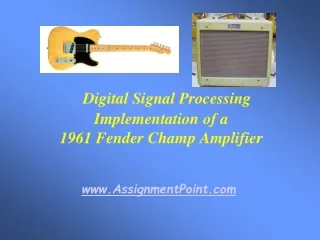
DSP Implementation of a1961 Fender Champ Amplifier James Siegle Advisor: Dr. Thomas L. Stewart May 6, 2003
Outline • Background • Objectives • Functional Description • Block Diagram • Lab Work • Final Results • Further Research • Conclusions • Acknowledgements
Background Solid-State Amplifiers • As solid-state technology has become more advanced in recent years, devices, such as transistors and ICs, are increasingly available to be used to design inexpensive guitar amplifiers. • However, these analog solid-state designs require much feedback to improve their linear transfer characteristic.
Background Solid-State Amplifiers • This heavy feedback results in a sharp clipping characteristic that produces successive harmonics with high amplitudes when the configuration is driven at a high volume. Reference: Barbour, Eric. "The Cool Sound of Tubes.” Ed., Michael J. Riezenman. IEEE Spectrum August 1998.
Background Tube Amplifiers • Guitar amplifiers based on vacuum tube designs have been known to produce a superior sound to solid-state amplifiers. • There are several theories to explain the tube amplifier’s superior sound as compared to the solid-state amplifier’s sound. • Overall, the tube amplifier configurations result in a frequency response with a dominant 1st harmonic component, followed by a 2nd harmonic component that is around half the magnitude of the 1st harmonic, and higher harmonics with decreasing amplitudes.
Background Tube Amplifiers • Lower harmonics have the most presence and thus produce a louder sound than solid-state amplifiers at high volumes. Reference: Barbour, Eric. "The Cool Sound of Tubes.” Ed., Michael J. Riezenman. IEEE Spectrum August 1998.
Background Tube Distortion vs. Solid-State Distortion Reference: Barbour, Eric. "The Cool Sound of Tubes.” Ed., Michael J. Riezenman. IEEE Spectrum August 1998.
Background Tube Amplifiers • Tube disadvantages: • short life time • fragility • storage inconvenience (bulky size) • high power and heat dissipation • high voltage operation • high impedances requiring matching transformers • high cost (Fender Champ cost = $1,000)
Objectives • The goal of the project is to reproduce the output characteristics of a 1961 Fender Champ from a guitar input with a DSP nonlinear modeling algorithm • The Champ has been chosen due to its popularity among vintage vacuum tube amplifiers and its simple design
Objectives • The DSP available for this project is the Texas Instruments TMS320C6711 Reference: http://www.ti.com/
Objectives • For MATLAB 6.5, there is an Embedded Target for the TMS320C6711 where a Simulink design can be translated to ANSI C standard code
Objectives • This Embedded Target feature allows more time improving the DSP algorithm for the amplifier model rather than spending hours learning the subtleties associated with the DSP board
Objectives • Several sets of data from sinusoidal and guitar inputs to the amplifier will be used to model the 1961 Fender Champ’s distortion characteristics • This method was used in the patents for similar projects (PAT. NO. 5,789,689 - Tube modeling programmable digital guitar amplification system) (PAT. NO. 6,350,943 - Electric instrument amplifier) Reference: http://www.uspto.gov/
Objectives • Since there are several differing views on the source of tube amplifiers’ unique distortion, this data collection approach is the most optimal and unified approach to the problem
Functional Description Analog Audio Signal from Guitar DSP with C/C++ or Assembly Digital Filters Guitar Cable Headphone Plug Attachment Audio Output with Tube Amplifier Sound • Inputs/Outputs • Inputs - analog audio signal from a guitar A/D interface and software based volume selection will regulate the filters’ behavior • Output - audio signal with tube amplifier effect
Functional Description Analog Audio Signal from Guitar DSP with C/C++ or Assembly Digital Filters Guitar Cable Headphone Plug Attachment • 12 volume settings similar to those provided with the 12-volume switch on the 1961 Fender Champ - (Only volume‘6’, the middle selection, has been implemented) • linear effects have be omitted due to lack of time (ie. echo, tremolo, reverberation, vibrato, etc.) Audio Output with Tube Amplifier Sound • Modes of Operation
Block Diagram Analog Audio Signal Input from Guitar Mode of Operation (Software) BP BP BP BP BP BP ... Nonlinear Transfer Characteristics BP BP BP BP BP BP ... Summer Parallel Bandpass FIR Filter Approach Final BP Equivalent Tube Amplifier Signal Output
Lab Work Approach • Complete and simulate model of 1961 Fender Champ obtained from nonlinear transfer characteristics of 16-bit audio output of 1961 Fender Champ Input Output
Lab Work Approach • Based on similarities and differences of nonlinear transfer characteristics, collect more 16-bit audio output of 1961 Fender Champ from sinusoidal inputs • Determine frequency ranges of approximate nonlinear transfer characteristics from data and guitar frequency chart • Record output from 1952 Fender Telecaster directly for 1961 Fender Champ response simulation verification • Verify highest frequency input from the guitar
Lab Work Guitar Note Frequency Chart Reference: http://home.pacbell.net/vaughn44/m3.music.notes.6.pdf
Lab Work Nonlinear Transfer Characteristic Determination from 16-bit Audio Output of 1961 Fender Champ Volume ‘12’ 523.25 (Hz)
Lab Work Nonlinear Transfer Characteristic Determination from 16-bit Audio Output of 1961 Fender Champ Volume ‘12’ 523.25 (Hz)
Lab Work Nonlinear Transfer Characteristic Determination from 16-bit Audio Output of 1961 Fender Champ • Eight more sinusoidal inputs were used to record 16-bit audio output of 1961 Fender Champ • Frequency, time domain, and transfer characteristics of this data were plotted and analyzed • ‘polyfit’ in MATLAB used to provide curve fits for eight selected transfer characteristics
Lab Work Highest Frequency from Guitar Time Domain Frequency Domain
Lab Work Input to 1961 Fender Champ at Volume ‘6’ (Output of Guitar) Time Domain Frequency Domain
Lab Work Fender Champ Response at Volume ‘6’ to 1952 Fender Telecaster Time Domain Frequency Domain
Lab Work • Nonlinear transfer characteristic curve fits were performed for eight frequency ranges where the curve was selected for one frequency to be approximate to characteristic curves of surrounding frequencies • The frequency ranges were the following: • 250 - 450 (Hz) • 450 - 700 (Hz) • 700 - 900 (Hz) • 900 - 1200 (Hz) • 1200 - 1500 (Hz) • 1500 - 2000 (Hz) • 2000 - 3000 (Hz) • 3000 - 4500 (Hz) • No significant information was present around DC
Lab Work • FIR coefficients were generated for these filters with FDATool in MATLAB due to the time spent fitting the nonlinear transfer characteristic curves Filter Design and Analysis Tool Window
Lab Work Previous Output of DSP Model of 1961 Fender Champ at Volume ‘6’ Time Domain Frequency Domain
Lab Work Output of DSP Model of 1961 Fender Champ at Volume ‘6’ Clipping seen from extra gain of 8 FIR filters being applied to nonlinear transfer characteristics defined for a -1 to 1 input range and incorrect transfer characteristic curve fits.
Final Results Simulated Output of DSP Model of 1961 Fender Champ at Volume ‘6’ Time Domain Frequency Domain
Final Results Comparison of Simulated DSP Model of 1961 Fender Champ at Volume ‘6’ to Actual Amplifier Output Time Domain Frequency Domain
Final Results Simulink DSP Model of 1961 Fender Champ at Volume ‘6’
Final Results Actual Output for DSP Model of 1961 Fender Champ at Volume ‘6’ • After setting the appropriate simulation parameters in Simulink to generate and build the C code to program the TMS320C6711 for the actual amplifier demonstration, the output exhibited a ‘clean’ sound for lower frequency guitar notes, and higher frequency guitar notes overdrove the speakers depending on the guitar’s volume gain setting • Currently, this output cannot be captured with any DSP Sinks in Simulink so that the actual frequency response from the board can be compared to the actual Champ output and the MATLAB simulation
Further Research • Investigate the source of the C code generation from a Simulink model with MATLAB 6.5’s Real-Time Workshop • Record the amplifier model output from the board with a DSP Sink in Simulink • Analyze the 1961 Fender Champ circuit based on the tube and transformer data available and based on PSPICE Simulations • Nonlinear transfer characteristics can be determined for separate stages of the circuit for wider frequency ranges • Amplifier model can be simplified • Transformer was shown to significantly affect the frequency response of the Champ around 1000 (Hz)
Further Research Transformer Effect on 1961 Fender Champ Frequency Response Around 1 (kHz) 1961 Fender Champ Output Preceding Transformer 1961 Fender Champ Output Following Transformer
Conclusions • The amplifier model sound from the board can be improved with analysis results successfully captured with a Simulink DSP Sink block • The 1961 Fender Champ DSP model was successfully implemented on a DSP evaluation board • Only designs with little complexity have been produced for past DSP boards • DSP boards are difficult to program as a result of poor accompanying documentation and external peripheral layouts • This project’s model was complex and implemented on a DSP evaluation board in less than a week • MATLAB 6.5’s Embedded Target for the TI C6000 feature is a powerful tool for implementing DSP-based designs without the time-consuming programming task
Acknowledgements • Dr. James H. Irwin, Jr. • Acoustics Laboratory equipment use for capturing the 1961 Fender Champ output • Rob Schaller • Computer and TMS320C6711 board use for initial demonstration of model • MathWorks, Inc. • Texas Instruments Embedded Target for the TI C6000 Platform