Download

1 / 50
500 likes | 521 Vues
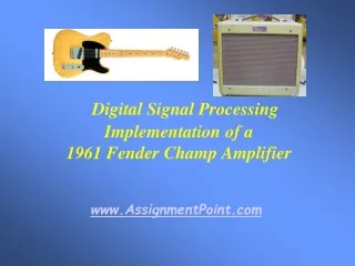
DSP Implementation of a 1961 Fender Champ Amplifier. James Siegle Advisor: Dr. Thomas L. Stewart December 10, 2002. Outline. Summary Background Project Justification Objectives Result Previous Work Patents Standards Project Description Functional Description Block Diagram

E N D
DSP Implementation of a1961 Fender Champ Amplifier James Siegle Advisor: Dr. Thomas L. Stewart December 10, 2002
Outline • Summary • Background • Project Justification • Objectives • Result • Previous Work • Patents • Standards • Project Description • Functional Description • Block Diagram • Operation Test • Lab Work • Parts List • Proposed EE452 Schedule
Summary Background Solid-State Amplifiers • As solid-state technology has become more advanced in recent years, devices, such as transistors and ICs, are increasingly available to be used to design inexpensive guitar amplifiers. • However, these analog solid-state designs require much feedback to improve their linear transfer characteristic.
Summary Background Solid-State Amplifiers • This heavy feedback results in a sharp clipping characteristic that produces successive harmonics with high amplitudes when the configuration is driven at a high volume. • There are several other disadvantages to transistor-based guitar amplifiers, but the above effect is most prevalent.
Summary Background Solid-State Amplifiers • This particular harmonic distortion can be seen below for the basic transistor amplifier configuration. (Input: Analog Oscillator with 2V rms@1(kHz) output) Reference: Barbour, Eric. "The Cool Sound of Tubes.” Ed., Michael J. Riezenman. IEEE Spectrum August 1998.
Summary Background Solid-State Amplifiers • These harmonics are unpleasant to the ear. • This inferior sound is the reason why vacuum tubes remain most popular in the guitar amplifier market.
Summary Background Tube Amplifiers • There are several theories to explain the tube guitar amplifier’s superior sound as compared to the solid-state amplifier’s sound. • Overall, the tube amplifier configurations result in a frequency response with a dominant 1st harmonic component, followed by a 2nd harmonic component that is around half the magnitude of the 1st harmonic, and higher harmonics with decreasing amplitudes.
Summary Background Tube Amplifiers • This characteristic frequency response results in the lower harmonics having the most presence and thus producing a louder sound than solid-state amplifiers at high volumes. • This behavior can be seen on the next slide for basic pentode and triode tube amplifier configurations.
Summary Background Tube Amplifiers (Input: Analog Oscillator with 2V rms@1(kHz) output) Reference: Barbour, Eric. "The Cool Sound of Tubes.” Ed., Michael J. Riezenman. IEEE Spectrum August 1998.
Summary Background Tube Amplifiers • Tube disadvantages: • short life time • fragility • storage inconvenience (bulky size) • high power and heat dissipation • high voltage operation • high impedances requiring matching transformers • high cost (Fender Champ cost = +$1,000)
Summary Project Justification • The disadvantages of tube guitar amplifiers can be resolved by emulating tube distortion characteristics with a device that already emulates other guitar-related characteristics (i.e. reverb, vibrato, etc.). • Low-cost digital signal processors (DSP’s) have been used to create several guitar effect standards.
Summary Objectives • The goal of the project is to reproduce the output characteristics of a 1961 Fender Champ with a DSP nonlinear modeling algorithm from a guitar input. • The Champ has been chosen due to its popularity among vintage tube amps and its simple design as seen in the next slide. • As a result, more time can be spent on improving the DSP algorithm.
Summary Objectives
Summary Results • When the project is completed, the output from speakers interfaced to the DSP board should match the sound of the Champ and resemble the characteristics of the data recorded in lab. • The result will be a superior tube amplifier sound implemented with a low-cost DSP. • Other tube amplifiers may be modeled from this specific DSP algorithm.
Previous Work Patents • Two patents pertaining to this project were found at U.S. Patent and Trademark Office website (http://www.uspto.gov) from “DSP” AND “guitar amplifiers” keywords.
Previous Work Patents • PAT. NO. 5,789,689 - Tube modeling programmable digital guitar amplification system • Does not specifically model the 1961 Fender Champ • Uses a sampling rate conversion algorithm to model the nonlinear transfer function of the tube circuitry. Later slides indicate that this method is not planned for the project.
Previous Work Patents • PAT. NO. 6,350,943 - Electric instrument amplifier • Does not specifically model the 1961 Fender Champ • Uses a similar DSP algorithm to model the tube nonlinearities, but also includes a tube configuration on the D/A output of the DSP board and a solid-state power circuit. Purpose of the project is to model the tube amplifier WITHOUT tubes or solid-state devices.
Previous Work Standards • No applicable standards to this project other than avoiding a >5 (V) input into the board. • If the amplifier is successfully modeled, other linear effects will be added to the design including reverb, vibrato, etc. in which there are several resources or standard techniques to produce these effects.
Project Description Functional Description DSP with C/C++ or Assembly Digital Filters Analog Audio Signal from Guitar or File • 12 volume settings similar to those provided with the 12-volume switch on the 1961 Fender Champ • echo, reverberation, fuzz, and vibrato Audio Output with Tube Amplifier Sound Volume Selection from Hardware/Software Overall Block Diagram • Inputs/Outputs • Inputs - analog audio signal from either a guitar A/D interface or a saved audio file and software or hardware based volume selection will regulate the filters’ behavior • Output - audio signal with tube amplifier effect • Modes of Operation
Project Description Block Diagram Analog Audio Signal Input from Guitar or File External Volume Selection Mode of Operation (Software) BP BP BP BP BP BP ... Summer Equivalent Tube Amplifier Signal Output Parallel Bandpass FIR Filter Approach
Project Description Block Diagram Analog Audio Signal Input from Guitar or File External Volume Selection Mode of Operation (Software) FFT FFT Parallel Filter Network Approach BP BP BP BP BP BP ... Summer IFFT Equivalent Tube Amplifier Signal Output
Project Description Block Diagram 2 LP Analog Audio Signal Input from Guitar or File 2 LP 2 HP Mode of Operation (Software) LP 2 External Volume Selection HP 2 HP 2 ... 2 LP 2 LP ... 2 HP Equivalent Tube Amplifier Signal Output ... 2 LP 2 HP ... 2 HP Multirate Signal Processing Approach Reference: Digital Signal Processing: Principles, Algorithms, and Applications. John G. Proakis, Dimitris G. Manolakis. Third Edition. 1996. pp. 832-834.
Project Description Operation Test Operation Test • Output will be recorded in laboratory and correlated with Fender Champ output data in MATLAB. Datasheet • This project involves modeling a tube amplifier response with a DSP algorithm and does not require a datasheet. • All necessary operation data for the Texas Instruments DSP board can be referenced in the provided manuals.
Project Description Lab Work Approach • Conduct several tests to determine Champ’s distinct output in time and frequency domains. Tests/Measurements • PSPICE simulations of basic tube amplifier configurations for 12AX7 triode and 6V6GT Pentode • Measure Fender Champ output with 16-bit audio A/D Converter with Cool Edit software in Acoustics lab for several sinusoidal inputs (see next slide) • Measure single-ended power tube stage output of Fender Champ before transformer
Project Description Lab Work Reference: http://home.pacbell.net/vaughn44/m-3.music.notes.6.pdf
Project Description Lab Work PSPICE Simulations Input (above), Output (below) 12AX7 Triode Amplifier
Project Description Lab Work PSPICE Simulations 12AX7 Triode Amplifier
Project Description Lab Work PSPICE Simulations Input (above), Output (below) 6V6GT Pentode Amplifier
Project Description Lab Work PSPICE Simulations 6V6GT Pentode Amplifier
Project Description Lab Work PSPICE Simulations • From the previous slides, the output of the triode amplifier configuration exhibits higher harmonic components beyond the 1st harmonic than the pentode configuration output. • Triode amplifier configuration still exhibits expected frequency response since the 2nd harmonic magnitude is slightly greater than half the 1st harmonic magnitude. • Both outputs of the amplifiers clip at the supply voltage. • PSPICE simulation of 1961 Fender Champ circuit can not be run since no transformer winding data is available, the transformer output on the amplifier is difficult to access, and the PSPICE transformer model is too ideal with no capacitive coupling.
Project Description Lab Work 16-bit Audio Output of 1961 Fender Champ
Project Description Lab Work 16-bit Audio Output of 1961 Fender Champ
Project Description Lab Work 16-bit Audio Output of 1961 Fender Champ
Project Description Lab Work 16-bit Audio Output of 1961 Fender Champ
Project Description Lab Work 16-bit Audio Output of 1961 Fender Champ
Project Description Lab Work 16-bit Audio Output of 1961 Fender Champ
Project Description Lab Work 16-bit Audio Output of 1961 Fender Champ
Project Description Lab Work 16-bit Audio Output of 1961 Fender Champ
Project Description Lab Work 16-bit Audio Output of 1961 Fender Champ
Project Description Lab Work 16-bit Audio Output of 1961 Fender Champ Summary • ‘Ringing’ effect seen from the Fender Champ output for input frequencies <1046.50 (Hz). • This ‘ringing’ is most dominant at 1046.50 (Hz) and results in 2nd and odd harmonic components with higher amplitudes than the first harmonic. • Odd harmonics are expected to be higher than even harmonics as seen in the next slide, but the first harmonic amplitude should not be smaller than successive harmonics.
Project Description Lab Work Transformer Frequency Response Reference: Barbour, Eric. "The Cool Sound of Tubes.” Ed., Michael J. Riezenman. IEEE Spectrum August 1998.
Project Description Lab Work Transformer Frequency Response Non-Ideal Transformer Transformer Frequency Response • From all the coupled capacitances, the transformer appears to exhibit a ‘resonance’ property that has the most effect on the output for a 1046.50 (Hz) input. • Champ characterized by poor low frequency response (F < 1046.50 (Hz)) due to the cheap output transformer.
Project Description Lab Work 6V6GT Output of 1961 Fender Champ Voltage Divider to Measure Output of Single-Ended Power Stage Vo = (R2/(R1+R2))*6V6GT output = 0.00662*6V6GT output PR1 = 1.33 (W), PR2 = 0.00890 (W) • Since tube circuits are characterized by high output voltages, a voltage divider connected to the 6V6GT output of the Fender Champ will allow the oscilloscope to measure the output at lower amplitudes.
Project Description Lab Work 6V6GT Output of 1961 Fender Champ Volume ‘3’
Project Description Lab Work 6V6GT Output of 1961 Fender Champ Volume ‘6’
Project Description Lab Work 6V6GT Output of 1961 Fender Champ Volume ‘12’
Project Description Lab Work 6V6GT Output of 1961 Fender Champ Summary • Similar output for volume ‘3’ setting as transformer output. • First harmonic is most dominant over successive harmonics for both volume ‘6’ and ‘12’ settings on the Fender Champ. • Volume ‘6’ does not drive the amplifier enough to produce second harmonic component with higher amplitude than the odd harmonics. • Harmonics greater than 10 have not been removed by transformer as expected. • More data points in the time domain would improve harmonic spikes in the frequency domain.
Project Description Lab Work Fender Champ Response to 1952 Fender Telecaster
Project Description Parts List • The goal of the project is to model the Fender Champ’s output characteristics. • If the DSP algorithm is completed and coded for the DSP board, some interfacing circuitry from a guitar cable to the ADC and from the DAC to a set of speakers will be required. • This interfacing circuitry will only consist of resistors, capacitors, a potentiometer, and a low voltage power amplifier, and these parts are available.
Project Description EE 452 Schedule • Next semester, the following schedule has been developed: • Weeks 1-4: Complete and Simulate model of Fender Champ in MATLAB from obtained 12AX7 and 6V6GT tube data sheets • Weeks 5-8: Complete Software to program the actual DSP board and interface the appropriate hardware to the ADC and DAC • Weeks 13-14: Senior 2003 Expo Preparation • Weeks 15-16: Senior Project Presentation • There is a 4-week window that is intended to allow for setbacks