Download

1 / 29
290 likes | 311 Vues
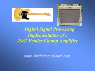
Reproducing the 1961 Fender Champ amplifier's sound using DSP modeling algorithm with nonlinear characteristics. Detailed functional and block diagrams included.

E N D
DSP Implementation of a1961 Fender Champ Amplifier James Siegle Advisor: Dr. Thomas L. Stewart March 11, 2003
Outline • Progress/Project Changes • Objectives Restatement • Functional Description • Block Diagram • Previous EE452 Schedule • Lab Work • Current Objectives • Current EE452 Schedule
Progress/Project Changes Objectives • The goal of the project is to reproduce the output characteristics of a 1961 Fender Champ from a guitar input with a DSP nonlinear modeling algorithm • The Champ has been chosen due to its popularity among vintage vacuum tube amplifiers and its simple design • The DSP available for this project is the Texas Instruments TMS320C6711
Progress/Project Changes Objectives
Progress/Project Changes Objectives • For MATLAB 6.5, there is an Embedded Target for the TMS320C6711 where a Simulink design can be translated to ANSI C standard code • Currently, this feature is being located for an inexpensive price • This addition will allow more time to be spent improving the DSP algorithm for the amplifier model rather than spending hours learning the subtlties of the DSP board
Progress/Project Changes Objectives • Several sets of data from sinusoidal and guitar inputs to the amplifier will be used to model the 1961 Fender Champ’s distortion characteristics • This approach was used in the patents for similar projects that were located earlier (PAT. NO. 5,789,689 - Tube modeling programmable digital guitar amplification system) (PAT. NO. 6,350,943 - Electric instrument amplifier)
Progress/Project Changes Objectives • Since there are several differing views on the source of tube amplifiers’ unique distortion, this data collection approach is the most optimal and unified approach to the problem
Progress/Project Changes Functional Description Analog Audio Signal from Guitar • 12 volume settings similar to those provided with the 12-volume switch on the 1961 Fender Champ - (Only three will be implemented where ‘3’ is the first audible volume, ‘6’ is the middle selection, and ‘12’ is overdriven level for amplifier • linear effects will be omitted due to lack of time DSP with C/C++ or Assembly Digital Filters Interfacing Circuitry to Guitar Cable Audio Output with Tube Amplifier Sound Volume Selection and Switching from Hardware Interface • Inputs/Outputs • Inputs - analog audio signal from either a guitar A/D interface or a saved audio file and software or hardware based volume selection will regulate the filters’ behavior • Output - audio signal with tube amplifier effect • Modes of Operation
Progress/Project Changes Block Diagram Analog Audio Signal Input from Guitar or File External Volume Selection Mode of Operation (Software) BP BP BP BP BP BP ... Nonlinear Transfer Characteristics Summer Equivalent Tube Amplifier Signal Output Parallel Bandpass FIR Filter Approach
Progress/Project Changes Block Diagram Analog Audio Signal Input from Guitar or File External Volume Selection Mode of Operation (Software) FFT FFT Parallel Filter Network Approach BP BP BP BP BP BP ... Nonlinear Transfer Characteristics Summer IFFT Equivalent Tube Amplifier Signal Output
Progress/Project Changes Block Diagram ... Analog Audio Signal Input from Guitar or File External Volume Selection 2 LP 2 LP ... 2 Mode of Operation (Software) HP ... LP 2 HP 2 ... ... ... ... HP ... 2 Nonlinear Transfer Characteristics 2 LP 2 LP 2 HP Equivalent Tube Amplifier Signal Output 2 LP 2 HP 2 HP Multirate Signal Processing Approach Reference: Digital Signal Processing: Principles, Algorithms, and Applications. John G. Proakis, Dimitris G. Manolakis. Third Edition. 1996. pp. 832-834.
Progress/Project Changes Block Diagram Current Selection • Parallel Bandpass FIR Filter Approach (1st approach) is the best approach due to the nonlinear transfer characteristic addition that is applied in the time domain and the large delay inherent to the Multirate Signal Processing Approach
Progress/Project Changes Previous EE452 Schedule Approach • Weeks 1-4: Complete and simulate model of Fender Champ in MATLAB from obtained 12AX7 and 6V6GT tube data sheets • Weeks 5-8: Complete software to program the actual DSP board and interface the appropriate hardware to the ADC and DAC • Weeks 13-14: Senior 2003 Expo Preparation • Weeks 15-16: Senior Project Presentation • There is a 4-week window that is intended to allow for setbacks
Progress/Project Changes Lab Work Approach Changes • Complete and simulate model of 1961 Fender Champ obtained from nonlinear transfer characteristics of 16-bit audio output of 1961 Fender Champ. • Based on similarities and differences of nonlinear transfer characteristics, take more 16-bit audio output of 1961 Fender Champ from sinusoidal inputs. • Determine eight frequency ranges of approximate nonlinear transfer characteristics from data and guitar frequency chart. • Verify highest frequency input from the guitar. • Record output from 1952 Fender Telecaster directly for 1961 Fender Champ response simulation verification.
Progress/Project Changes Lab Work Reference: http://home.pacbell.net/vaughn44/m-3.music.notes.6.pdf
Progress/Project Changes Lab Work Nonlinear Transfer Characteristic Determination from 16-bit Audio Output of 1961 Fender Champ Volume ‘12’ 523.25 (Hz)
Progress/Project Changes Lab Work Nonlinear Transfer Characteristic Determination from 16-bit Audio Output of 1961 Fender Champ
Progress/Project Changes Lab Work Nonlinear Transfer Characteristic Determination from 16-bit Audio Output of 1961 Fender Champ • Eight more sinusoidal inputs were used to record 16-bit audio output of 1961 Fender Champ. • Frequency, time domain, and transfer characteristics of this data were plotted and analyzed. • Highest note was plucked on 1952 Fender Telecaster and its frequency response recorded. • Output from 1952 Fender Telecaster directly was recorded. • ‘polyfit’ in MATLAB used to provide curve fits for eight selected transfer characteristics.
Progress/Project Changes Lab Work Highest Frequency from Guitar
Progress/Project Changes Lab Work Input to 1961 Fender Champ at Volume ‘6’ (Output of Guitar)
Progress/Project Changes Lab Work Fender Champ Response at Volume ‘6’ to 1952 Fender Telecaster
Progress/Project Changes Lab Work • Nonlinear transfer characteristic curve fits were performed for eight frequency ranges where the curve was selected for one frequency to be approximate to characteristic curves of surrounding frequencies. • The frequency ranges were the following: • 0 - 250 (Hz) • 250 - 450 (Hz) • 450 - 700 (Hz) • 700 - 900 (Hz) • 900 - 1500 (Hz) • 1500 - 2000 (Hz) • 2000 - 3000 (Hz) • 3000 - 5000 (Hz)
Progress/Project Changes Lab Work • FIR coefficients were generated for these filters with FDATool in MATLAB due to the time spent fitting the nonlinear transfer characteristic curves • The nonlinear transfer characteristics for Volume ‘6’ were performed on guitar output
Progress/Project Changes Lab Work Output of DSP Model of 1961 Fender Champ at Volume ‘6’
Progress/Project Changes Lab Work Output of DSP Model of 1961 Fender Champ at Volume ‘6’ Clipping seen from gain of 7 FIR filters being applied to nonlinear transfer characteristics defined for a -1 to 1 input range.
Progress/Project Changes Lab Work Comparison of DSP Model of 1961 Fender Champ at Volume ‘6’ to Actual Amplifier Output
Progress/Project Changes Lab Work • The number of frequency ranges was reduced to 7 since the 0 - 250 (Hz) nonlinear transfer characteristic output amplified the lower frequencies • Lower frequencies did not have much presence in the Fender Champ output earlier • The lowest frequency from the guitar is 329.63 (Hz) from the chart earlier
Current Objectives • Discover flaw with DSP model of 1961 Fender Champ in MATLAB code • Implement the MATLAB code simulation in Simulink • If there is no time to get the code ready for the Texas Instruments TMS320C6711 DSP board or the Embedded Target cannot be obtained, the processed output from MATLAB will be sent through the board’s D/A converter for demonstration • Otherwise, the code will be generated for the DSP, and the guitar will be interfaced to the A/D input such that the entire dynamic range of the A/D is utilized for processing
Current EE452 Schedule • The current schedule is as follows: • Weeks 1-7: Simulate model of Fender Champ in MATLAB from nonlinear transfer characteristics • Weeks 8-9: Generate code for Texas Instruments TMS320C6711 DSP board with MATLAB or manually • Weeks 10-12: Complete Software to program the actual DSP board and interface the appropriate hardware to the ADC and DAC • Weeks 13-14: Senior 2003 Expo Preparation • Weeks 15-16: Senior Project Presentation