Last class
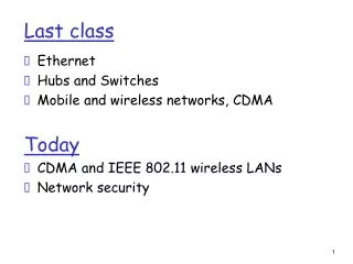
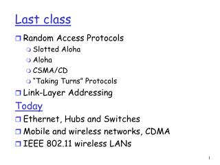
Last class. Random Access Protocols Slotted Aloha Aloha CSMA/CD “Taking Turns” Protocols Link-Layer Addressing Today Ethernet, Hubs and Switches Mobile and wireless networks, CDMA IEEE 802.11 wireless LANs. Pros single active node can continuously transmit at full rate of channel

Last class
E N D
Presentation Transcript
Last class • Random Access Protocols • Slotted Aloha • Aloha • CSMA/CD • “Taking Turns” Protocols • Link-Layer Addressing Today • Ethernet, Hubs and Switches • Mobile and wireless networks, CDMA • IEEE 802.11 wireless LANs
Pros single active node can continuously transmit at full rate of channel highly decentralized: only slots in nodes need to be in sync simple Cons collisions, wasting slots idle slots clock synchronization Slotted ALOHA (Efficiency 0.36)
Pure (unslotted) ALOHA • unslotted Aloha: simpler, no synchronization • when frame first arrives • transmit immediately • collision probability increases: • frame sent at t0 collides with other frames sent in [t0-1,t0+1]
“Taking Turns” MAC protocols Token passing: • control token passed from one node to next sequentially. • token message • concerns: • token overhead • latency • single point of failure (token) Polling: • master node “invites” slave nodes to transmit in turn • concerns: • polling overhead • latency • single point of failure (master)
Question: how to determine MAC address of B knowing B’s IP address? ARP: Address Resolution Protocol • Each IP node (Host, Router) on LAN has ARP table • ARP Table: IP/MAC address mappings for some LAN nodes < IP address; MAC address; TTL> • TTL (Time To Live): time after which address mapping will be forgotten (typically 20 min) 237.196.7.78 1A-2F-BB-76-09-AD 237.196.7.23 237.196.7.14 LAN 71-65-F7-2B-08-53 58-23-D7-FA-20-B0 0C-C4-11-6F-E3-98 237.196.7.88
Overview • Ethernet • Hubs and Switches • Mobile and wireless networks, CDMA • IEEE 802.11 wireless LANs
Ethernet Frame Structure Sending adapter encapsulates IP datagram (or other network layer protocol packet) in Ethernet frame Preamble: • 7 bytes with pattern 10101010 followed by one byte with pattern 10101011 • used to synchronize receiver, sender clock rates
No slots adapter doesn’t transmit if it senses that some other adapter is transmitting, that is, carrier sense transmitting adapter aborts when it senses that another adapter is transmitting, that is, collision detection Before attempting a retransmission, adapter waits a random time, that is, random access Ethernet uses CSMA/CD
1. Adaptor receives datagram from net layer & creates frame 2. If adapter senses channel idle, it starts to transmit frame. If it senses channel busy, waits until channel idle and then transmits 3. If adapter transmits entire frame without detecting another transmission, the adapter is done with frame ! 4. If adapter detects another transmission while transmitting, aborts and sends jam signal (48 bits) 5. After aborting, adapter enters exponential backoff: after the mth collision, adapter chooses a K at random from {0,1,2,…,2m-1}. Adapter waits K·512 bit times and returns to Step 2 Ethernet CSMA/CD algorithm
Jam Signal: make sure all other transmitters are aware of collision; 48 bits Bit time: .1 microsec for 10 Mbps Ethernet ;for K=1023, wait time is about 50 msec Exponential Backoff: Goal: adapt retransmission attempts to estimated current load heavy load: random wait will be longer first collision: choose K from {0,1}; delay is K· 512 bit transmission times after second collision: choose K from {0,1,2,3}… after ten collisions, choose K from {0,1,2,3,4,…,1023} Ethernet’s CSMA/CD (more)
CSMA/CD efficiency • Tprop = max prop between 2 nodes in LAN • ttrans = time to transmit max-size frame • Efficiency goes to 1 as tprop goes to 0 • Goes to 1 as ttrans goes to infinity • Much better than ALOHA, but still decentralized, simple, and cheap
twisted pair hub 10BaseT and 100BaseT • 10/100 Mbps rate; latter called “fast ethernet” • T stands for Twisted Pair • Nodes connect to a hub: “star topology”; 100 m max distance between nodes and hub
Gbit Ethernet • uses standard Ethernet frame format • allows for point-to-point links and shared broadcast channels • in shared mode, CSMA/CD is used; short distances between nodes required for efficiency • uses hubs, called here “Buffered Distributors” • Full-Duplex at 1 Gbps for point-to-point links • 10 Gbps now !
Overview • Ethernet • Hubs and Switches • Wireless links, characteristics, CDMA • IEEE 802.11 wireless LANs
twisted pair hub Hubs Hubs are essentially physical-layer repeaters: • bits coming from one link go out all other links • at the same rate • no frame buffering • no CSMA/CD at hub: adapters detect collisions • provides net management functionality • can disconnect a malfunctioning adapter
Interconnecting with hubs Pros: • Enables interdepartmental communication • Extends max distance btw. nodes • If a hub malfunctions, the backbone hub can disconnect it Cons: • Collision domains are transferred into one large, common domain • Cannot interconnect 10BaseT and 100BaseT hubs hub hub hub hub
Switch • Link layer device • stores and forwards Ethernet frames • examines frame header and selectively forwards frame based on MAC dest address • when frame is to be forwarded on segment, uses CSMA/CD to access segment • transparent • hosts are unaware of presence of switches • plug-and-play, self-learning • switches do not need to be configured
switch hub hub hub Forwarding 1 3 2 • How to determine onto which LAN segment to forward frame? • Looks like a routing problem...
Self learning • A switch has a switch table • entry in switch table: • (MAC Address, Interface, Time Stamp) • stale entries in table dropped (TTL can be 60 min) • switchlearns which hosts can be reached through which interfaces • when frame received, switch “learns” location of sender: incoming LAN segment • records sender/location pair in switch table
Filtering/Forwarding When switch receives a frame: index switch table using MAC dest address if entry found for destinationthen{ if dest on segment from which frame arrivedthen drop the frame else forward the frame on interface indicated } else flood forward on all but the interface on which the frame arrived
Switch example Suppose C sends frame to D address interface switch 1 1 1 2 3 A B E G 3 2 hub hub hub A I F D G B C H E • Switch receives frame from from C • notes in bridge table that C is on interface 1 • because D is not in table, switch forwards frame into interfaces 2 and 3 • frame received by D
Switch example Suppose D replies back with frame to C. address interface switch 1 1 2 3 1 A B E G C hub hub hub A I F D G B C H E • Switch receives frame from from D • notes in bridge table that D is on interface 2 • because C is in table, switch forwards frame only to interface 1 • frame received by C
switch hub hub hub Switch: traffic isolation • switch installation breaks subnet into LAN segments • switch filters packets: • same-LAN-segment frames not usually forwarded onto other LAN segments • segments become separate collision domains collision domain collision domain collision domain
Switches: dedicated access A • Switch with many interfaces • Hosts have direct connection to switch • No collisions; full duplex Switching: A-to-A’ and B-to-B’ simultaneously, no collisions C’ B switch C B’ A’
More on Switches • cut-through switching: frame forwarded from input to output port without first collecting entire frame • slight reduction in latency • combinations of shared/dedicated, 10/100/1000 Mbps interfaces
Institutional network mail server to external network web server router switch IP subnet hub hub hub
Switches vs. Routers • both store-and-forward devices • routers: network layer devices (examine network layer headers) • switches are link layer devices • routers maintain routing tables, implement routing algorithms • switches maintain switch tables, implement filtering, learning algorithms
Overview • Ethernet • Hubs and Switches • Mobile and wireless networks, CDMA • IEEE 802.11 wireless LANs
Background: # wireless (mobile) phone subscribers now exceeds # wired phone subscribers! computer nets: laptops, palmtops, PDAs two important (but different) challenges communication over wireless link handling mobile user who changes point of attachment to network Wireless and Mobile Networks
wireless hosts • laptop, PDA, IP phone • run applications • may be stationary (non-mobile) or mobile • wireless does not always mean mobility network infrastructure Elements of a wireless network
base station • typically connected to wired network • relay - responsible for sending packets between wired network and wireless host(s) in its “area” • e.g., cell towers 802.11 access points network infrastructure Elements of a wireless network
network infrastructure Elements of a wireless network wireless link • typically used to connect mobile(s) to base station • multiple access protocol coordinates link access • various data rates, transmission distance
infrastructure mode • base station connects mobiles into wired network • handoff: mobile changes base station providing connection into wired network network infrastructure Elements of a wireless network
Elements of a wireless network Ad hoc mode • no base stations • nodes can only transmit to other nodes within link coverage • nodes organize themselves into a network: route among themselves
Wireless Link Characteristics Differences from wired link …. • decreased signal strength: radio signal attenuates as it propagates through matter (path loss) • interference from other sources: standardized wireless network frequencies (e.g., 2.4 GHz) shared by other devices (e.g., phone); • multipath propagation: radio signal reflects off objects ground, arriving ad destination at slightly different times …. make communication across (even a point to point) wireless link much more “difficult”
B A C C C’s signal strength A’s signal strength B A space Wireless network characteristics Multiple wireless senders and receivers create additional problems (beyond multiple access): Hidden terminal problem • B, A hear each other • B, C hear each other • A, C can not hear each other means A, C unaware of their interference at B Signal fading: • B, A hear each other • B, C hear each other • A, C can not hear each other interferring at B