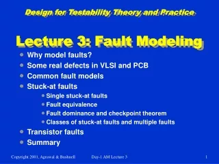
Design for Testability Theory and Practice Lecture 7: Sequential ATPG
200 likes | 423 Vues
Design for Testability Theory and Practice Lecture 7: Sequential ATPG. Problem of sequential circuit ATPG Time-frame expansion Nine-valued logic ATPG implementation and drivability Complexity of ATPG Cycle-free and cyclic circuits Asynchronous circuits Summary. Sequential Circuits.

Design for Testability Theory and Practice Lecture 7: Sequential ATPG
E N D
Presentation Transcript
Design for Testability Theory and PracticeLecture 7: Sequential ATPG • Problem of sequential circuit ATPG • Time-frame expansion • Nine-valued logic • ATPG implementation and drivability • Complexity of ATPG • Cycle-free and cyclic circuits • Asynchronous circuits • Summary Day-2 AM Lecture 7
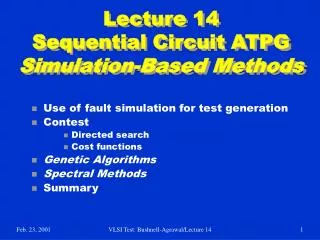
Sequential Circuits • A sequential circuit has memory in addition to combinational logic. • Test for a fault in a sequential circuit is a sequence of vectors, which • Initializes the circuit to a known state • Activates the fault, and • Propagates the fault effect to a primary output • Methods of sequential circuit ATPG • Time-frame expansion methods • Simulation-based methods Day-2 AM Lecture 7
Example: A Serial Adder Bn An 1 1 s-a-0 D 1 1 D X Cn Cn+1 X 1 Combinational logic Sn X FF Day-2 AM Lecture 7
Time-Frame Expansion Bn-1 An-1 Bn An Time-frame -1 Time-frame 0 1 1 1 1 s-a-0 s-a-0 D X D D 1 1 D 1 Cn-1 X D 1 Cn 1 Cn+1 X 1 Combinational logic Combinational logic 1 Sn-1 Sn X D FF Day-2 AM Lecture 7
Concept of Time-Frames • If the test sequence for a single stuck-at fault contains n vectors, • Replicate combinational logic block n times • Place fault in each block • Generate a test for the multiple stuck-at fault using combinational ATPG with 9-valued logic Vector – n +1 Vector – 1 Vector 0 Fault Unknown or given Init. state Time- Frame - n+1 Time- frame 0 Time- frame -1 Next state State variables Comb. block PO – 1 PO 0 PO – n +1 Day-2 AM Lecture 7
Example for Logic Systems FF1 B A FF2 s-a-1 Day-2 AM Lecture 7
Five-Valued Logic (Roth)0,1, D, D, X A 0 A 0 s-a-1 s-a-1 D D X X X FF1 FF1 X D D FF2 FF2 B B X X Time-frame 0 Time-frame -1 Day-2 AM Lecture 7
Nine-Valued Logic (Muth)0,1, 1/0, 0/1,1/X, 0/X, X/0, X/1, X A 0 A X s-a-1 s-a-1 X/1 0/1 0/X 0/X X FF1 FF1 0/1 X X/1 FF2 FF2 B B X 0/1 Time-frame 0 Time-frame -1 Day-2 AM Lecture 7
Implementation of ATPG • Select a PO for fault detection based on drivability analysis. • Place a logic value, 1/0 or 0/1, depending on fault type and number of inversions. • Justify the output value from PIs, considering all necessary paths and adding backward time-frames. • If justification is impossible, then use drivability to select another PO and repeat justification. • If the procedure fails for all reachable POs, then the fault is untestable. • If 1/0 or 0/1 cannot be justified at any PO, but 1/X or 0/X can be justified, the the fault is potentially detectable. Day-2 AM Lecture 7
Drivability Example (11, 16) (22, 17) (10, 15) (10, 16) d(0/1) = d(1/0) = 32 8 s-a-1 d(0/1) = 4 d(1/0) = d(0/1) = d(1/0) = 20 8 8 (5, 9) (4, 4) (17, 11) d(0/1) = 9 d(1/0) = (6, 10) (CC0, CC1) = (6, 4) d(0/1) = 120 d(1/0) = 27 FF 8 d(0/1) = 109 d(1/0) = 8 CC0 and CC1 are SCOAP combinational controllabilities d(0/1) and d(1/0) of a line are effort measures for driving a specific fault effect to that line Day-2 AM Lecture 7
Complexity of ATPG • Synchronous circuit -- All flip-flops controlled by clocks; PI and PO synchronized with clock: • Cycle-free circuit – No feedback among flip-flops: Test generation for a fault needs no more than dseq + 1 time-frames, where dseq is the sequential depth. • Cyclic circuit – Contains feedback among flip-flops: May need 9Nff time-frames, where Nff is the number of flip-flops. • Asynchronous circuit – Higher complexity! Time- Frame max-1 Time- Frame max-2 Time- Frame -2 Time- Frame -1 Time- Frame 0 Smax S2 S1 S0 S3 max = Number of distinct vectors with 9-valued elements= 9Nff Day-2 AM Lecture 7
Cycle-Free Circuits • Characterized by absence of cycles among flip-flops and a sequential depth, dseq. • dseq is the maximum number of flip-flops on any path between PI and PO. • Both good and faulty circuits are initializable. • Test sequence length for a fault is bounded by dseq + 1. Day-2 AM Lecture 7
F2 2 F3 F1 Level = 1 3 Cycle-Free Example Circuit F2 2 All faults are testable in this circuit. F3 F1 3 Level = 1 s - graph dseq = 3 Day-2 AM Lecture 7
Cyclic Circuit Example Modulo-3 counter Z CNT F2 F1 s - graph F2 F1 Day-2 AM Lecture 7
Modulo-3 Counter • Cyclic structure – Sequential depth is undefined. • Circuit is not initializable. No tests can be generated for any stuck-at fault. • After expanding the circuit to 9Nff = 81, or fewer, time-frames ATPG program calls any given target fault untestable. • Circuit can only be functionally tested by multiple observations. • Functional tests, when simulated, give no fault coverage. Day-2 AM Lecture 7
s - graph F2 F1 Adding Initializing Hardware Initializable modulo-3 counter Z CNT F2 F1 s-a-0 s-a-1 CLR s-a-1 s-a-1 Untestable fault Potentially detectable faults Day-2 AM Lecture 7
Benchmark Circuits Circuit PI PO FF Gates Structure Seq. depth Total faults Detected faults Potentially detected faults Untestable faults Abandoned faults Fault coverage (%) Fault efficiency (%) Max. sequence length Total test vectors Gentest CPU s (Sparc 2) s1494 8 19 6 647 Cyclic -- 1506 1379 2 30 97 91.6 93.4 28 559 19183 s1238 14 14 18 508 Cycle-free 4 1355 1283 0 72 0 94.7 100.0 3 308 15 s1196 14 14 18 529 Cycle-free 4 1242 1239 0 3 0 99.8 100.0 3 313 10 s1488 8 19 6 653 Cyclic -- 1486 1384 2 26 76 93.1 94.8 24 525 19941 Day-2 AM Lecture 7
Summary • Combinational ATPG algorithms are extended: • Time-frame expansion unrolls time as combinational array • Nine-valued logic system • Justification via backward time • Cycle-free circuits: • Require at most dseq+ 1 time-frames • Always initializable • Cyclic circuits: • May need 9Nff time-frames • Circuit must be initializable • Partial scan can make circuit cycle-free • Asynchronous circuits: Not discussed • See,M. L. Bushnell and V. D. Agrawal, Essentials of Electronic Testing for Digital, Memory and Mixed-Signal VLSI Circuits, Springer, 2000, Chapter 8. Day-2 AM Lecture 7
Exercise 3: Lecture 7 • Which type of circuit is easier to test? Circle one in each: • Combinational or sequential • Cyclic or cycle-free • Synchronous or asynchronous • What is the maximum number of input vectors that may be needed to initialize a cycle-free circuit with k flip-flops? Day-2 AM Lecture 7
Exercise 3 Answers • Which type of circuit is easier to test? Circle one in each: • Combinational or sequential • Cyclic or cycle-free • Synchronous or asynchronous • What is the maximum number of input vectors that may be needed to initialize a cycle-free circuit with k flip-flops? k vectors. Because that is the maximum sequential depth possible. An example is a k bit shift register. Day-2 AM Lecture 7