Advanced Test Generation for Sequential Circuits: Time-Frame Expansion and ATPG Complexity
220 likes | 337 Vues
This lecture focuses on the complexities of Automatic Test Pattern Generation (ATPG) for sequential circuits, emphasizing time-frame expansion techniques. It covers the differences between cycle-free and cyclic circuits, the role of nine-valued logic, and the impact of drivability on test generation. The lecture explores various methods for sequencing tests, establishing known states, and propagating faults to outputs. Additionally, it highlights the challenges posed by asynchronous circuits and summarizes the methods for analyzing testability in both synchronous and asynchronous designs.

Advanced Test Generation for Sequential Circuits: Time-Frame Expansion and ATPG Complexity
E N D
Presentation Transcript
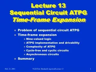
Lecture 13Sequential Circuit ATPGTime-Frame Expansion • Problem of sequential circuit ATPG • Time-frame expansion • Nine-valued logic • ATPG implementation and drivability • Complexity of ATPG • Cycle-free and cyclic circuits • Asynchronous circuits • Summary VLSI Test: Bushnell-Agrawal/Lecture 13
Sequential Circuits • A sequential circuit has memory in addition to combinational logic. • Test for a fault in a sequential circuit is a sequence of vectors, which • Initializes the circuit to a known state • Activates the fault, and • Propagates the fault effect to a primary output • Methods of sequential circuit ATPG • Time-frame expansion methods • Simulation-based methods VLSI Test: Bushnell-Agrawal/Lecture 13
Example: A Serial Adder Bn An 1 1 s-a-0 D 1 1 D X Cn Cn+1 X 1 Combinational logic Sn X FF VLSI Test: Bushnell-Agrawal/Lecture 13
Time-Frame Expansion Bn-1 An-1 Bn An Time-frame -1 Time-frame 0 1 1 1 1 s-a-0 s-a-0 D X D D 1 1 D 1 Cn-1 X D 1 Cn 1 Cn+1 X 1 Combinational logic Combinational logic 1 Sn-1 Sn X D FF VLSI Test: Bushnell-Agrawal/Lecture 13
Concept of Time-Frames • If the test sequence for a single stuck-at fault contains n vectors, • Replicate combinational logic block n times • Place fault in each block • Generate a test for the multiple stuck-at fault using combinational ATPG with 9-valued logic Vector -n+1 Vector -1 Vector 0 Fault Unknown or given Init. state Next state State variables Time- frame 0 Time- frame -n+1 Time- frame -1 Comb. block PO -1 PO 0 PO -n+1 VLSI Test: Bushnell-Agrawal/Lecture 13
Example for Logic Systems FF1 B A FF2 s-a-1 VLSI Test: Bushnell-Agrawal/Lecture 13
Five-Valued Logic (Roth)0,1, D, D, X A 0 A 0 s-a-1 s-a-1 D D X X X FF1 FF1 X D D FF2 FF2 B B X X Time-frame 0 Time-frame -1 VLSI Test: Bushnell-Agrawal/Lecture 13
Nine-Valued Logic (Muth)0,1, 1/0, 0/1,1/X, 0/X, X/0, X/1, X A 0 A X s-a-1 s-a-1 X/1 0/1 0/X 0/X X FF1 FF1 0/1 X X/1 FF2 FF2 B B X 0/1 Time-frame 0 Time-frame -1 VLSI Test: Bushnell-Agrawal/Lecture 13
Implementation of ATPG • Select a PO for fault detection based on drivability analysis. • Place a logic value, 1/0 or 0/1, depending on fault type and number of inversions. • Justify the output value from PIs, considering all necessary paths and adding backward time-frames. • If justification is impossible, then use drivability to select another PO and repeat justification. • If the procedure fails for all reachable POs, then the fault is untestable. • If 1/0 or 0/1 cannot be justified at any PO, but 1/X or 0/X can be justified, the the fault is potentially detectable. VLSI Test: Bushnell-Agrawal/Lecture 13
Drivability Example (11, 16) (22, 17) (10, 15) (10, 16) d(0/1) = d(1/0) = 32 8 s-a-1 d(0/1) = 4 d(1/0) = d(0/1) = d(1/0) = 20 8 8 (5, 9) (4, 4) (17, 11) d(0/1) = 9 d(1/0) = (6, 10) (CC0, CC1) = (6, 4) d(0/1) = 120 d(1/0) = 27 FF 8 d(0/1) = 109 d(1/0) = 8 CC0 and CC1 are SCOAP combinational controllabilities d(0/1) and d(1/0) of a line are effort measures for driving a specific fault effect to that line VLSI Test: Bushnell-Agrawal/Lecture 13
Complexity of ATPG • Synchronous circuit -- All flip-flops controlled by clocks; PI and PO synchronized with clock: • Cycle-free circuit – No feedback among flip-flops: Test generation for a fault needs no more than dseq + 1 time-frames, where dseq is the sequential depth. • Cyclic circuit – Contains feedback among flip-flops: May need 9Nff time-frames, where Nff is the number of flip-flops. • Asynchronous circuit – Higher complexity! Time- Frame max-1 Time- Frame max-2 Time- Frame -2 Time- Frame -1 Time- Frame 0 Smax S2 S1 S0 S3 max = Number of distinct vectors with 9-valued elements= 9Nff VLSI Test: Bushnell-Agrawal/Lecture 13
Cycle-Free Circuits • Characterized by absence of cycles among flip-flops and a sequential depth, dseq. • dseq is the maximum number of flip-flops on any path between PI and PO. • Both good and faulty circuits are initializable. • Test sequence length for a fault is bounded by dseq + 1. VLSI Test: Bushnell-Agrawal/Lecture 13
F2 2 F3 F1 3 Level = 1 Cycle-Free Example Circuit F2 2 F3 F1 3 Level = 1 s - graph dseq = 3 All faults are testable. See Example 8.6. VLSI Test: Bushnell-Agrawal/Lecture 13
Cyclic Circuit Example Modulo-3 counter Z CNT F2 F1 s - graph F2 F1 VLSI Test: Bushnell-Agrawal/Lecture 13
Modulo-3 Counter • Cyclic structure – Sequential depth is undefined. • Circuit is not initializable. No tests can be generated for any stuck-at fault. • After expanding the circuit to 9Nff = 81, or fewer, time-frames ATPG program calls any given target fault untestable. • Circuit can only be functionally tested by multiple observations. • Functional tests, when simulated, give no fault coverage. VLSI Test: Bushnell-Agrawal/Lecture 13
s - graph F2 F1 Adding Initializing Hardware Initializable modulo-3 counter Z CNT F2 F1 s-a-0 s-a-1 CLR s-a-1 s-a-1 Untestable fault Potentially detectable fault VLSI Test: Bushnell-Agrawal/Lecture 13
Benchmark Circuits Circuit PI PO FF Gates Structure Seq. depth Total faults Detected faults Potentially detected faults Untestable faults Abandoned faults Fault coverage (%) Fault efficiency (%) Max. sequence length Total test vectors Gentest CPU s (Sparc 2) s1494 8 19 6 647 Cyclic -- 1506 1379 2 30 97 91.6 93.4 28 559 19183 s1238 14 14 18 508 Cycle-free 4 1355 1283 0 72 0 94.7 100.0 3 308 15 s1196 14 14 18 529 Cycle-free 4 1242 1239 0 3 0 99.8 100.0 3 313 10 s1488 8 19 6 653 Cyclic -- 1486 1384 2 26 76 93.1 94.8 24 525 19941 VLSI Test: Bushnell-Agrawal/Lecture 13
Asynchronous Circuit • An asynchronous circuit contains unclocked memory often realized by combinational feedback. • Almost impossible to build, let alone test, a large asynchronous circuit. • Clock generators, signal synchronizers, flip-flops are typical asynchronous circuits. • Many large synchronous systems contain small portions of localized asynchronous circuitry. • Sequential circuit ATPG should be able to generate tests for circuits with limited asynchronous parts, even if it does not detect faults in those parts. VLSI Test: Bushnell-Agrawal/Lecture 13
Asynchronous Model Synchronous PIs CK Combinational Feedback Paths: Feedback set Feedback-free Combinational Logic C PPI PPO Synchronous POs CK Clocked Flip-flops System Clock, CK Feedback delays Fast model Clock, FMCK Modeling circuit is Shown in orange. VLSI Test: Bushnell-Agrawal/Lecture 13
Time-Frame Expansion Vector k PI Feedback set Feedback set C CK C FMCK C FMCK C FMCK PPO PPI Asynchronous feedback stabilization PO Time-frame -k-1 Time-frame -k+1 Time-frame k VLSI Test: Bushnell-Agrawal/Lecture 13
Asynchronous Example s-a-0 0 0 1 0 1 1 0 1 s-a-0 s-a-0 1 0 1 1 0 1 X X 0 1 0 1 s-a-0 s-a-0 s-a-0 s-a-1 s-a-0 Vectors 1 2 3 4 Outputs 1 2 3 4 Gentest results: Faults: total 23, detected 15, untestable 8 (shown in red), potentially detectable none Vectors: 4 Sparc 2 CPU time: test generation 33ms, fault simulation 16ms VLSI Test: Bushnell-Agrawal/Lecture 13
Summary • Combinational ATPG algorithms are extended: • Time-frame expansion unrolls time as combinational array • Nine-valued logic system • Justification via backward time • Cycle-free circuits: • Require at most dseq time-frames • Always initializable • Cyclic circuits: • May need 9Nff time-frames • Circuit must be initializable • Partial scan can make circuit cycle-free (Chapter 14) • Asynchronous circuits: • High complexity • Low coverage and unreliable tests • Simulation-based methods are more useful (Section 8.3) VLSI Test: Bushnell-Agrawal/Lecture 13