Download
1 / 28
430 likes | 1.53k Vues
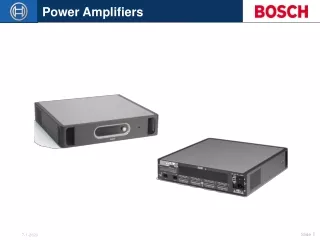
POWER AMPLIFIERS. Classification of power amplifiers. POWER AMPLIFIERS. Required To deliver a large current to a small load resistance e.g. audio speaker; or to deliver a large voltage to a large load resistance e.g. switching power supply;

E N D
POWER AMPLIFIERS Classification of power amplifiers
POWER AMPLIFIERS • Required • To deliver a large current to a small load resistance e.g. audio speaker; or to deliver a large voltage to a large load resistance e.g. switching power supply; • To be of low output resistance in order to avoid loss of gain and to maintain linearity (to minimize harmonic distortion) • To deliver power to the load efficiently
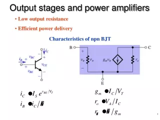
POWER TRANSISTORS - BJT Transistor limitations 1 maximum rated current, 2 maximum rated voltage, 3 maximum rated power, and 4 maximum allowed temperature.
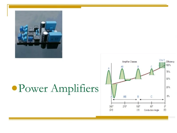
Classes of Amplifiers They are grouped together based on their Q-points on the DC load line.
In class-A; the transistor conducts during the whole cycle of sinusoidal input signal
In class-B; the transistor conducts during one-half cycle of input signal
In class-AB; the transistor conducts for slightly more than half a cycle of input signal
In class-C; the transistor conducts for less than half a cycle of input signal
Cass–A operation For maximum swing ( +ve and –ve), transistor is biased such that the Q point is at centre of the load line. The transistor conducts for a full cycle of the input signal
Instantaneous power dissipation in transistor is; For sinusoidal input signal; And; For maximum possible swing;
Therefore; (See graphical representation)
When the input signal = 0, the transistor must be capable of handling a continuous power of; Efficiency; PL = average ac power to the load PS = average power supplied by the source (VCC)
For maximum possible swing; Power supplied by the source; Maximum theoretical efficiency of class A amplifier is therefore 25% The efficiency;
Cass–B operation Consists of complementary pair electronic devices One conducts for one half cycle of the input signal and the other conducts for another half of the input signal Both devices are off when the input is zero (See Figure)
Complementary push-pull circuit Assuming ideal transistor; when vI = 0; both Qn & Qp are off; when vI > 0; Qn conducts & Qp is off; when vI < 0; Qp conducts & Qn is off An approximate class-B circuit comprising complementary BJT pair working in push-pull configuration.
Assuming cut-in voltage of transistor is 0.6 V, vO = 0 for a range 0.6 V < vI < 0.6 V. The transfer characteristic becomes non-linear (See Figure) The range where both transistors are simultaneously off known as the dead band The output will be distorted – crossover distortion (See Figure) Crossover distortion can be eliminated by biasing the transistor with small quiescent current – class-AB
The instantaneous power in Qnis; for 0 < t < and for < t < 2 The average power in Qnis;
(symmetry) Differentiating for maximum PQn with respect to Vp gives us; Since each power source supplies half sinewave of current, the average value is;
The total power supplied by the two sources is; The power delivered to the load is; The efficiency is;
Maximum efficiency occures when Under this condition; Maximum theoretical efficiency of class B amplifier is therefore 78.5%
Cass–AB operation Small quiescent bias on each output transistor to eliminate crossover distortion Small ICQ flows through each transistor in the absent of input signal
Cass–C operation Transistor conducts for less than half a cycle of input signal • Tuned circuit is required. • Used for RF amplifier. • Efficiency > 78.5% B – E junction is reverse-biased to obtain Q-point beyond cut-off.