Download
1 / 22

E N D
Exponential Tracking Control of Hydraulic Proportional Directional Valve and Cylinder via Integrator BacksteppingJ. Chen†, W. E. Dixon‡, J. R. Wagner†, D. M. Dawson††Departments of Mechanical and Electrical/Computer EngineeringClemson University, Clemson, SC 29634 ‡Oak Ridge National Laboratory, Oak Ridge, TN 37831
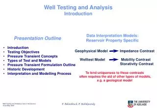
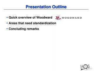
Presentation Outline • Literature Review • Hydraulic System Model • Differentiable Approximation for Fluid Dynamics • Control Objective • Error System Development • Nonlinear Controller Design • Stability Analysis • Numerical Results • Summary
Literature Review • Gamble et al. (1994) presented a comparison of sliding mode control with state feedback and PID control for proportional solenoid valves. • Vossoughi et al. (1995) created, and experimentally verified, a globally linearizing feedback control law for electro-hydraulic valves. • Bobrow et al. (1996) developed an adaptive hydraulic servo-valve controller which uses full-state feedback for simultaneous parameter identification and tracking control. • Alleyne (1996) developed a Lyapunov-based control algorithm for the control of an electro-hydraulic actuator. A gradient parameter adaptation scheme was included for compensating parametric model uncertainties. • Zheng et al. (1998) proposed a nonlinear adaptive learning algorithm for a proportional valve to accommodate valve dead zones, valve flow saturation, and cylinder seal friction. • Bu et al. (1999) designed a discontinuous projection based adaptive robust controller for single-rod hydraulic actuators with time-varying unknown inertia.
X Hydraulic System Model – Cylinder Dynamics • Cylinder dynamics can be written as • The hydraulic flow force F is defined as Externally applied load (neglected for simplicity) (spring / damping term)
Hydraulic System Model – Pressures and Flows • The pressures dynamics of the piston and rod side can be written as • Fluid flow of the piston and rod side can be written as Remark: The hydraulic cylinder is assumed to be constructed such that some volume always remains in the piston and rod sides of the cylinder
Hydraulic System Model – Spool Dynamics P z P S T m s P P R P Q Q R P • The spool dynamics can be related to as follows • The spool dynamics can now be rewritten as (solenoid control force) neglected for simplicity (spring / damping term)
Control Voltage Proportional Solenoid Hydraulic Valve Spool Position LVDT Bosch NG6 Servo - Solenoid Control Valve
1 h(2, z) 1 (1+st) R Fg VL VS s + - f(, z) g(VL) z id ir + + VR i Hydraulic System Model – Solenoid Model
Differentiable Approximation for Fluid Dynamics • Differentiable approximation for the fluid dynamics real model where Remark: Supply and tank pressures are assumed to satisfy the following inequalities
Control Objective • The control objective is to force the piston position of a hydraulic cylinder to track a time varying reference trajectory. • It is assumed that all system parameters are known (Exact Model Knowledge) and all signals are measurable (Full State Feedback) • Define the piston tracking error as • Define the filtered tracking error as where is a positive control gain • It can be shown that if , then
After taking the time derivative of , the primary open-loop error system can be written as • Based on the previous equation and the subsequent stability analysis, the desired hydraulic flow force is designed as follows • After substituting the control design into the open-loop error system, the closed-loop error system for can be obtained as Obtained by adding and subtracting the desired hydraulic flow force (Auxillary force tracking error signal)
Error System Development • After taking the time derivative of , using the pressure dynamics, the second open-loop error system is obtained as where, • The auxillary control input is now designed as • Based on this design, the closed loop error system for becomes Desired spool position function
Error System Development (cont.) • After taking the time derivative of , the open-loop error system for can be obtained • Then the open-loop error system for can be rewritten as where, here, the notation denotes the partial derivative of with respect to • The desired spool velocity is now designed as (Spool velocity tracking error)
Error System Development (cont.) • After substituting into the open-loop error system for ,we obtain • After taking the time derivative of , the open-loop dynamics for can be determined as follows • Based on the subsequent stability analysis, the control input is designed as follows which allows us to write the closed loop dynamics for as follows
Stability Analysis • A non-negative function is defined as follows • Then V(t) can be lower and upper bounded as follows where, • After taking the time derivative of V(t) and substituting the closed loop error system, we obtain
Cylinder Dynamics Pressure Dynamics Electrical Dynamics Solenoid Dynamics Pressure Control Control Strategy • After utilizing the above inequalities, we can show Pressure Position Force Flow Control Voltage Desired Position Error Desired Force Desired Flow Desired Pressure Cylinder Control Solenoid Control Electrical Control Controller
Numerical Results • A PD and nonlinear controller shall track a sinusoidal position for the cylinder piston subject to nonlinear load conditions within 3% of the specified position • The desired trajectory is • Comparison of Commanded solenoid voltages for PD and nonlinear controllers • Comparison of Fluid pressures for PD and nonlinear controllers • Comparison of Positions and tracking errors for PD and Nonlinear controllers
0.02 0.15 0.01 0.1 Cylinder Position (m) Position Error (m) 0 0.05 -0.01 0 0 20 40 60 0 20 40 60 time(s) time(s) 0.02 0.15 0.01 0.1 Cylinder Position (m) Position Error (m) 0 0.05 -0.01 0 0 20 40 60 0 20 40 60 time(s) time(s) Numerical Results PD Controller Nonlinear Controller
900 900 850 850 Pressure Pr (psi) Pressure Pp (psi) 800 800 750 750 700 700 0 20 40 60 0 20 40 60 time(s) time(s) 900 900 850 850 Pressure Pp (psi) Pressure Pr (psi) 800 800 750 750 700 700 0 20 40 60 0 20 40 60 time(s) time(s) Numerical Results PD Controller Nonlinear Controller
PD Controller 10 Solenoid voltage (Volts) 5 0 0 10 20 30 40 50 60 time(s) Nonlinear Controller 10 5 Solenoid voltage (Volts) 0 0 10 20 30 40 50 60 time(s) Numerical Results
Experimental Test Stand Control Valve Piston side Pressure Transducer Rod side Pressure Transducer LVDT Cylinder
Summary • Present the mathematical models for hydraulic system • Develop a differentiable approximation for the fluid flow dynamics • Proposal a model based nonlinear controller for hydraulic system. • Validate the controller with numerical and experimental results • Investigate both PD and nonlinear controller