Recap in last lecture
320 likes | 604 Vues
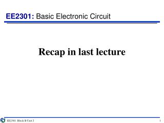
Recap in last lecture. Impedance Summary. “Complex” Impedance. So far, examples of impedances are either purely real or purely imaginary Consider the following combination. Since in R & L are in series, total impedance is: Z = R + j ω L. L. R. General form: Z = R + j X.

Recap in last lecture
E N D
Presentation Transcript
Recap in last lecture EE2301: Block B Unit 2
Impedance Summary EE2301: Block B Unit 1
“Complex” Impedance • So far, examples of impedances are either purely real or purely imaginary • Consider the following combination Since in R & L are in series, total impedance is: Z = R + jωL L R General form: Z = R + jX Imaginary part is called the reactance Real part is called the AC resistance We can combine impedance values like in DC circuits but now treating values as complex numbers and taking into account the effect of frequency. EE2301: Block B Unit 1
Impedance: example 1 Problem 4.61 Work out the impedance (Z) seen across the terminals Given: ω = 4 rad/s If w= 4 rad/s, Z = 2W resistive If w=2 rad/s, Z=1.6-j0.3W capacitive If w=8 rad/s, Z=0.4+j1.2W inductive The network impedance is frequency dependant EE2301: Block B Unit 1
Block B Unit 2 Outline • Examples on analyzing AC circuits • See Supplementary Notes on Phasors and Complex Numbers for information on methods • Work through supplementary questions on phasors if you have no prior knowledge on complex numbers • Frequency response (effect of frequency) • Low pass filter • High pass filter • Resonance G. Rizzoni, “Fundamentals of EE” Section 4.4 G. Rizzoni, “Fundamentals of EE” Sections 6.1-6.2 EE2301: Block B Unit 2
Analysis methodology 1. Any sinusoidal signal may be mathematically represented in one of two ways: a time-domain form and a frequency-domain (or phasor) form Note the jω in the notation V( jω), indicating the ejωtdependence of the phasor. In the remainder of this chapter, bold uppercase quantities indicate phasor voltages or currents. 2. A phasor is a complex number, expressed in polar form, consisting of a magnitude equal to the peak amplitude of the sinusoidal signal and a phase angle equal to the phase shift of the sinusoidal signal referenced to a cosine signal. 3. When one is using phasor notation, it is important to note the specific frequency ω of the sinusoidal signal, since this is not explicitly apparent in the phasor expression. EE2301: Block B Unit 2
Impedance: example 1 Problem 4.61 Work out the impedance (Z) seen across the terminals Z(w) EE2301: Block B Unit 1
A very basic example to start Find VC(t) in terms of R and C given that VS(t) = VScos(ωt) First find the respective impedances in the circuit, Capacitor: 1/jωC Resistor: R Next transform sinusoids to phasors, Voltage source: VS Apply voltage divider rule for R and C in series, VC = (1/jωC)/[R + (1/jωC)]VS VC = R/[1 + jωRC]VS VC = AVScos(ωt + θ); where A = R/√[1 + (ωRC)2] and θ = -tan-1(ωRC) EE2301: Block B Unit 2
Multiple sources: different phase Given that: V1(t) = 15cos(377t + π/4) and V2(t) = 15cos(377t + π/12) Find the total voltage across the two sources V1(t) ~ V2(t) ~ The first and most important thing to note here is that the 2 voltage sources are not in phase. Hence V1 + V2 must be derived by vector addition. For this, we must convert the sinusoids to complex numbers. V1 = 15cos(π/4) + j15sin(π/4); V2 = 15cos(π/12) + j15sin(π/12) Therefore, V1 + V2 = 15[cos(π/4) + cos(π/12)] + j15[sin(π/4) + sin(π/12)] V1 + V2 = 25.095 + j14.489 = 38.33cos(ωt + 0.857) V EE2301: Block B Unit 2
Multiple sources: different frequency Given that i1(t) = A1cos(ω1t) and i2(t) = A2cos(ω2t) Find the current through the load Note that if we blindly follow the same procedure used in the previous case, we would arrive at the wrong answer. This is because the frequencies of the sources are now different. The phasor form only describes the magnitude and phase but not the frequency of the component: so take note of this whenever there is a change in frequency. In this case, we can think about each sources to be independent of the other. Hence we can revert to the use of superposition. Current through load = i1 + i2 = A1cos(ω1t) + A2cos(ω2t) Two frequency components Note that the phase relationship between the two sources is not consequential in this case EE2301: Block B Unit 2
AC superposition example (Pt 1) Is(t) = 0.5cos[2π(100t)] A; Vs(t) = 20cos[2π(1000t)] V Find VR1(t) and VR2(t) Note first that the frequencies of the two sources are different, so we can apply superposition. Short-circuit the voltage source and find VR1 and VR2 due only to iS, We find that R1 and R2 are in parallel and therefore: VR1 = VR2 = IS*(R1||R2) = 18.75cos[2π(100t)] V EE2301: Block B Unit 2
AC superposition example (Pt 2) Open-circuit the current source and find VR1 and VR2 due only to VS, We can then apply voltage divider rule: VR1 = [R1/(R1+R2)]VS; VR2 = [R2/(R1+R2)]VS VR1 = 0.75VS; VR2 = 0.25VS VR1 = 15cos[2π(1000t)] V; VR2 = 5cos[2π(1000t)] V Finally we sum up the voltage components at each frequency: VR1 = 18.75cos[2π(100t)] + 15cos[2π(1000t)] V; VR2 = 18.75cos[2π(100t)] + 5cos[2π(1000t)] V EE2301: Block B Unit 2
Phasor techniques: Example 1 Problem 4.50 Determine i3(t) in the following circuit for ω = 377 rad/s if: i1(t) = 141.4 cos(ωt + 2.356) mA i2(t) = 50 sin(ωt – 0.927) mA We can simply use KCL to find i3 since i1 and i2 are both already known. But to do so, we must first convert the sinusoids into phasor form and then to complex numbers to add or subtract the currents. I1 = 141.4cos(2.356) + j141.4sin(2.356) = -100 + j100 mA Since i2 is a sine function, we should convert it to a cosine function first to get the correct phase. i2(t) = 50 cos[ωt - 0.927 - π/2] = 50 cos(ωt – 2.498) I2 = 50cos(2.498) - j50sin(2.498) = -40 – j30 mA I3 = I1 – I2 = -60 + j130 => i3(t) =143.1 cos(ωt + 2) mA EE2301: Block B Unit 2
Phasor techniques: Example 2 Problem 4.51 Determine the current through Z3 if VS1 = VS2 = 170 cos(377t) V; Note that the two voltage sources are in phase, so we can just add up their magnitudes. VT = VS1 + VS2 = 340 cos(377t) This is the voltage across Z3, so therefore we can find the current through Z3: EE2301: Block B Unit 2
Phasor techniques: Example 3 Problem 4.55 Find the voltage across the capacitor The resistor, inductor and capacitor are all in parallel with the current source. So we can find the effective impedance seen by the current source and use this to find the voltage. v(t) = 16.64 cos(2t – 0.983) V EE2301: Block B Unit 2
Phasor techniques: Example 4 Problem 4.52 Determine the frequency so that Ii and Vo in the following circuit are in phase. ZS = 13000 + j3ω, R = 120Ω, L = 19mH, C = 220pF When Ii and Vo are in phase, the admittance and the impedance seen across Vo must have a phase equal to zero. If the phase Y is zero, then its value must be purely real Imaginary part must be equal to zero We find in this case that L/C >> R, hence EE2301: Block B Unit 2
Frequency response • We have seen that changing the frequency affects the currents and voltages in a circuit • This is due to changes in the impedances of the various components in a circuit • This affects the working frequency range of a particular device or circuit • Hence it is important to find out the frequency response of a circuit • The frequency response of a circuit is a measure of the variation of a load-related voltage or current as a function of the frequency of the excitation signal • We typically express this in terms of variation in output voltage as a function of source voltage: EE2301: Block B Unit 2
Frequency response example 1 Compute the frequency response HV(jωL) for the following circuit: R1 = 1kΩ; C = 10µF; RL = 10kΩ First find the combined impedance of the capacitor and resistor in parallel: Now apply voltage divider rule: EE2301: Block B Unit 2
Frequency response example 2 Compute the frequency response HZ(jω) for the following circuit: R1 = 1kΩ; L = 2mH; RL = 4kΩ First find the combined impedance of the inductor and resistor in parallel: Now apply current divider rule: EE2301: Block B Unit 2
Low pass filter Let us consider the response of the output Vo in relation to the input Vi. We keep the amplitude of Vi constant but vary its frequency ω. By voltage divider rule: Observations: When ω approaches zero, Vo/Vi approaches 1 and phase is close to zero When ω becomes large, Vo/Vi approaches zero and phase is close to –π/2 Allows lower frequency signal to pass and filters off higher frequency signals EE2301: Block B Unit 2
Response of low pass filter Allows lower frequency signals to pass and filters off higher frequency signals Note that when ω = 1/RC, the imaginary and real parts of the denominator will be equal. Magnitude = 1/√2 Phase = -π/4 (or -45o) This frequency is called the cutoff frequency (ω0) of the filter, and gives an indication of the filtering characteristics of the circuit. EE2301: Block B Unit 2
High pass filter Let us consider the response of the output Vo in relation to the input Vi. We keep the amplitude of Vi constant but vary its frequency ω. By voltage divider rule: Observations: When ω approaches zero, Vo/Vi approaches zero and phase is close to π/2 When ω becomes large, Vo/Vi approaches 1 and phase is close to 0 Allows higher frequency signals to pass and filters off lower frequency signals EE2301: Block B Unit 2
Response of high pass filter Allows higher frequency signals to pass and filters off lower frequency signals Note that when ω = 1/RC, the imaginary and real parts of the denominator will be equal. Magnitude = 1/√2 Phase = π/4 (or 45o) This frequency is called the cutoff frequency (ω0) of the filter, and gives an indication of the filtering characteristics of the circuit. EE2301: Block B Unit 2
Bandpass filter Let us consider the response of the output Vo in relation to the input Vi. We keep the amplitude of Vi constant but vary its frequency ω. By voltage divider rule: We can see that the output will be maximum when the imaginary part of the denominator is zero: (ωL/R) – [1/(ωRC)] = 0 ω2 = 1/(LC) When this happens, the impedances of the capacitor and inductor are equal and opposite. This is known as resonance. EE2301: Block B Unit 2
Response of band pass filter The shape of the band pass is governed by the quality factor defined as: It is also defined using the half-power bandwidth Δω The larger the value of Q, the sharper the band pass so one can have a narrow band or broad band filter EE2301: Block B Unit 2
Half power bandwidth Half power bandwidth: The frequency span whereby the power is half of the maximum at resonance. A half in power corresponds to a scale factor of 1/√2 for the voltage frequency response. This occurs when the real and imaginary parts are of the same magnitude with each other. EE2301: Block B Unit 2
Guess it? EE2301: Block B Unit 2
QR Code to Survey http://proj.ee.cityu.edu.hk/lectures/default.php?u=ac EE2301: Block B Unit 2
What kind of filter is it? 1) Low-Pass Filter 2) Band-Pass Filter 3) High-Pass Filter 4) Band-Stop Filter EE2301: Block B Unit 2
What kind of filter is it? R L 1) Low-Pass Filter 2) Band-Pass Filter 3) High-Pass Filter 4) Band-Stop Filter EE2301: Block B Unit 2
What kind of filter is it? L R 1) Low-Pass Filter 2) Band-Pass Filter 3) High-Pass Filter 4) Band-Stop Filter EE2301: Block B Unit 2
What kind of filter is it? 1) Low-Pass Filter 2) Band-Pass Filter 3) High-Pass Filter 4) Band-Stop Filter EE2301: Block B Unit 2