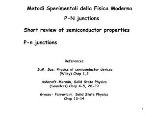
p-n junctions: forward bias
p-n junctions: forward bias. Effectively injecting electrons into n-type, holes into p-type Electrons repelled from contact with battery, move to junction Holes repelled from contact, move to junction Recombination continuous at junction ~ conduction occurs No depletion zone

p-n junctions: forward bias
E N D
Presentation Transcript
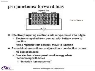
p-n junctions: forward bias • Effectively injecting electrons into n-type, holes into p-type • Electrons repelled from contact with battery, move to junction • Holes repelled from contact, move to junction • Recombination continuous at junction ~ conduction occurs • No depletion zone • Free electrons lose quantum of energy when recombining with holes • “Injection luminescence” Source: Dutton
p-n junctions: reverse bias • Electrons sucked out of n-type region, holes out of p-type region • Depletion zone increases • No conduction; device insulates Source: Dutton
Laser technical parameters • Spectral width • Linewidth • Coherence length and coherence time • Power • Stability • Switching time and modulation • Tuning range (tunable lasers only)
Spectral width • Semiconductor lasers do not produce light at a single wavelength • Produce range of wavelengths, called “spectral width” of laser • Usually produce around 8 frequencies or “modes” • Result from fact that resonating cavity is long enough for several different multiples of wavelength • Width ~ 6 to 8 nm • Not produced simultaneously, but laser jumps randomly among them • In each mode for a few nanoseconds • Laser output power does not vary—just wavelength
Spectral width (continued) • Importance • Spectral width determines chromatic dispersion • Better for lasers than LEDs • In WDM systems, wavelengths must be packed closely together, requiring narrow spectral width • Narrow spectral width signals can be subject to nonlinear effects which are undesirable Source: Dutton
Linewidth • Width of individual frequencies discussed in connection with spectral width • Referred to as “lines” • Affects modulation and detection techniques • Frequency, phase modulation, coherent detection require linewidth to bandwidth ratio of 1:100 • Newer methods using optical amplifiers have mitigated this requirement somewhat
Coherence time • Time that laser emits a given wavelength (line) • Distance light travels in that time called “coherence length” • Times • LED: ~0.5 x 10⁻¹² second • Simple laser: ~0.5 x 10⁻⁹ second • High quality laser: ~10-6 second
Frequency or wavelength stability • Refers to changes in emitted wavelength of a laser with time, temperature changes, etc. • Not as important in single-channel systems with incoherent detection • Critical for WDM systems • Fabry-Perot lasers can very 0.4 nm/degree • Lasers modulated by on-off keying (OOK) produce “chirp” at beginning of each pulse • Transient frequency shift up to several gigahertz • Operation of laser causes heating of cavity and changes in its parameters
Switching time and modulation • Methods • On-off keying (OOK): switching laser on and off to generate pulses • Up to thousands of teraHz ~ 0.5 fsec • Some can be by frequency shift keying (FSK) • Changing frequency of laser by varying bias current • Requires coherent detection • External modulation techniques which operate on the light beam after it is generated • Used in systems operating faster than 1 Gbps • Employ crystals which change optical properties in response to electrical signals
Tuning range • Some newer lasers can be tuned • Not fast • Tuning cannot be used as modulation technique • Not continuous: laser jumps between modes
Laser operation—energy levels Source: Dutton
Laser operation—population inversion • Stimulated emission not enough to make a laser • Problem is that electrons in ground state will absorb photons at same wavelength at which those in higher state emit them • No net release of photons • But probabilities of the two are different • Must fix this problem by having number of electrons in higher energy x probability of emission > than number in lower energy state x probability of absorption N(eh) x pe > N(el) x pa • Called “population inversion”
Laser operation—sequence of events • Energy applied—electrons in high state appear • Spontaneous emission begins, most is lost • Some hits mirrors at correct angle, is reflected back • Photons bouncing back and forth stimulate others • Number quickly builds up • Some leaves through partially reflecting mirror • Power increases until amount leaving = input power – losses • Reflectivity ~6% in semiconductor lasers Fig 65 Source: Dutton
Fabry-Perot lasers • Simplest kind of semiconductor laser • LED + pair of mirrors • Distance between mirrors is integral multiple of half wavelengths • Wavelengths not resonant encounter destructive interference • Frequencies: • 630-650 nm (pointers) • 790 nm (CD players) • 850, 1310, 1550 nm (fiber optics) • Size: a few hundred microns Source: Dutton
Fabry-Perot lasers (continued) • Wavelength produced can be calculated as l = 2nCl / x where x = 1, 2, 3…; Cl is cavity length, n is RI of active medium • Typical cavity length ~ 100-200 microns • Several hundred wavelengths Source: Dutton
Fabry-Perot lasers (continued) • Produces wide spectral width due to its construction • 5-8 nm • Not suitable for the most critical applications • Extended distances • Coherent detection • WDM • Emerging beam tends to diverge, requiring focusing
Fabry-Perot lasers (continued) • Performance can be improved by modifying design to eliminate unwanted frequencies • Before reaching lasing threshold • Common way: put diffraction grating in cavity • Effect is to deflect all but a narrow range of frequencies so that they do not hit mirrors at correct angle • Linewidth of 0.2-0.3 nm possible • Can use external cavity with diffraction grating on one mirror • Linewidth of 10 MHz
Glitches in real lasers • Line broadening • Turn-on delay • Mode hopping • Chirp • Relaxation oscillations • Relative Intensity Noise (RIN) • Phase noise • Intercavity noise • Drift
Line broadening • Can’t make a “perfect” laser • Single line • Infinitely narrow wavelength range • Line broadening occurs • Homogeneous • Mainly quantum mechanical effects • Dt x DE > h/2p • Gives rise to range of energies and frequencies • Inhomogeneous • Thermal vibration of atoms • Impurities
Turn on delay • Delay from application of power to production of coherent light • Spectrum sharpens as full power reached Source: Dutton
Mode hopping • Cause by “hole burning” • After short time in operation, laser depletes excited atoms in center of cavity (dominant path) • Not possible to get power to all of active regions at an even rate • “Hole” is burned in path of dominant mode • Reduces its power • Other modes gain power • Occurs in 10s of psec Source: Dutton
Chirp • Most serious of transient effects • RI of cavity changes after turn on • Density of charge carriers drops • Temperature in cavity abruptly rises • Results in rapid change in center wavelength produced • Downward “chirp” produced • Wavelength shifts to longer wavelength than at start of pulse • Requires use of external modulators for extremely high speed transmission rates (> 1 Gbps)
Relaxation oscillations • Short term fluctuations in intensity of light produced • Result from depletion of high energy electrons • Lasing action reduced or disappears • High energy electrons have to build up again • Usually damps out, but if laser not properly designed, will continue indefinitely Source: Dutton
Relative intensity noise (RIN) • Random intensity fluctuations in output of laser • Due to random nature of spontaneous emissions • Some spontaneous emissions can resonate and are amplified
Phase noise • Related to RIN • New spontaneous emissions different in phase from previous emissions • Leads to random changes in phase of emitted light • Cannot be suppressed as it is a consequence of way lasers operate • Not important in amplitude modulated systems
Intercavity noise • Caused by reflections from components other than mirrors at ends of cavity • Because reflections are of the correct wavelength, they are amplified • Leads to undesired fluctuations in light production • Sources • Nearby: laser-to-fiber coupling • More distant: Optical components down the fiber • Can be suppressed with optical isolator which prevents such reflections from passing through
Drift • After a period of operation, laser operation will change because critical parameters change • Known as “drift” • Temperature rises, changing cavity length and therefore resonant wavelength • Age of device
Construction of real lasers: simple laser • Made (grown) from a single crystal • Planes of crystal exactly parallel • Cleaved instead of cut along planes of crystal • Gives exactly parallel mirrors at ends • No silvering required: interface of semiconductor medium (RI ~ 3.5) and air effectively forms mirror • No lasing in vertical or lateral modes • Lasing across width of active region • Difficult to get light into fiber
Simple laser (continued) Source: Dutton
Construction of real lasers: gain guided • Gain guided operation • Basic idea: control lasing region by controlling entry of power into active region • Limit area of electrical contact by inserting (growing) insulator • Improved performance • Narrow beam • Spectral width 5-8 nm • 8-20 lines • Linewidth .005 nm Source: Dutton
Construction of real lasers: index guided • In addition to insulator, reduce width of active region • Put strips of semiconductor material with high bandgap energy on either side of active region • Active region bounded on all sides by material of lower RI • Call “index guided” • Improved performance • Spectral width 1-3 nm • 1-5 lines • Linewidth 0.001 nm Source: Dutton
Operational characteristics • Minimum, maximum levels (0, 1 states) • At 0, laser set just above lasing threshold • At 1, laser set just below maximum threshold • Extinction ratio: light at full power / light at 0 level • Quoted in db • Temperature control • Needed for long-term stability • High performance communications lasers incorporate thermoelectric coolers and associated control circuitry • Power control • Monitor light level, adjust output with feedback circuit • Monitor diode at back of laser
Distributed feedback lasers (DFB) • Designed to solve problems of standard FP lasers • Spectral width too wide • Too much mode hopping • Put diffraction grating (Bragg grating) into laser cavity • Effectively selects certain wavelengths through constructive interference • Period of corrugations is multiple of desired l • Grating actually put just below cavity • Too much attenuation if put in cavity • Still works because of E field penetration into adjacent layers
DFB laser (continued) • Chirp problem still exists, but much smaller than FB lasers because grating determines wavelength, not energy gap • Advantages • Narrow linewidths ~50 kHz • Low chirp • Low RIN Source: Dutton
Problems with DFB lasers • Extremely sensitive to reflections • Cause widening of wavelength • Requires integrated isolator • Sensitive to temperature variations • Average temperature • Rapid changes produced by certain bit patterns • Significant fluctuations in output • Stabilized by feedback circuit with PIN diode • Relatively high cost
Improving switching speed • Inherent device physics limits switching speed • Extremely high speed devices use external modulator • Modulator can be integrated with laser • Common type referred to as “Integrated absorption modulators” or “Electro-absorption modulators” (EML) Source: Dutton
Q-switching • Similar to previous case, except mirror moved to right hand end • When laser in OFF state, active medium pumped • Can turn on very quickly • Generates high power pulse • Can be used to generate solitons
Tunable lasers • Under development • One method: adjust Bragg grating in DBR • Current can change parameters of Bragg grating • Results in selection of different wavelength Source: Alcatel
Tunable lasers (continued) Source: Alcatel
Vertical Cavity Surface Emitting Laser (VCSEL) • Emit from surface instead of edge • Better light pattern for coupling into fiber • Low power (~1 mw) but much higher than most LEDs • Size 12-20 microns • 850 nm or 950 nm • Low threshold currents • Low modulation currents • High stability—no special circuitry required • Very high modulating bandwidth—up to 2.4 GHz
VCSEL (continued) Source: Dutton