Understanding ARM CPU Architecture and Instruction Execution
This overview simplifies the structure and functioning of ARM CPUs, emphasizing essential components like the main memory (DDR) and bus systems (FSB, DMI). It explains microarchitecture, covering datapaths, control units, and instruction execution phases—fetch, decode, execute, and the role of the program counter (PC). Important ARM instructions such as data processing, memory access, and branch instructions are highlighted. The decoding process of fetched instructions is described, detailing how operands and opcode are extracted and utilized in executing commands within the ARM CPU.

Understanding ARM CPU Architecture and Instruction Execution
E N D
Presentation Transcript
ARM CPU Internal I Prof. Taeweon Suh Computer Science Education Korea University
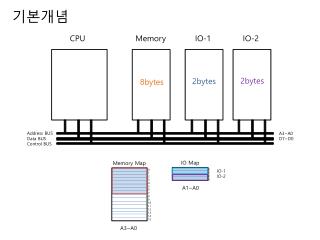
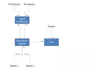
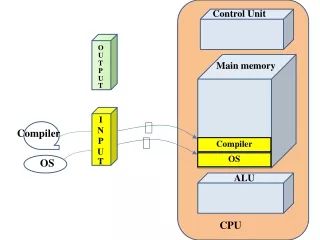
Overview • For the sake of your understanding, we simplify the CPU and its system structure CPU Main Memory (DDR) FSB (Front-Side Bus) North Bridge Memory (Instruction, data) Real-PC system ARM CPU Address Bus DMI (Direct Media I/F) Simplified South Bridge Data Bus
Actual ARM Connection • ARM CPU has separate connections to memory (caches) ARM920T Memory Instruction fetch Instruction Cache Address Bus ARM CPU core Address Bus Data Bus Address Bus Data Bus Data Cache Instruction/ Data access Data Bus Data access
Overview • Microarchitecture is composed of datapath and control • Datapathoperates on words of data • Datapath elements are used to operate on or hold data within a processor • Datapath elements include the register file, ALU, muxes, and memory • Control tells the datapath how to execute instructions • Control unit receives the current instruction from the datapath and tells the datapath how to execute that instruction • Specifically, the control unit produces mux select, register enable, ALU control, and memory write signals to control the operation of the datapath • Essential ARM instructions • Data processing instructions: add, sub, cmp, and, or • Memory access instructions: ldr, str • Branch instructions: b, bl
Instruction Execution in CPU • Generic steps of the instruction execution in CPU • Fetch uses the program counter (PC) to supply the instruction address and fetch instruction from memory • Decoding decodes instruction and reads operands • Extract opcode: determine what operation should be done • Extract operands: register numbers or immediate from fetched instruction • Execution • Use ALU to calculate (depending on instruction class) • Arithmetic or logical result • Memory address for load/store • Branch target address • Access memory for load/store • Next Fetch • PC target address or PC + 4 Address Bus Instruction/ Data Memory ARM CPU core Fetch with PC Data Bus PC = PC +4 Address Bus Execute Data Bus Decode
Instruction Fetch • What is PC on reset in ARM? • PC = 0x0000_0000 ARM CPU core Increment by 4 for the next instruction Add Memory reset clock 4 PC Out Address 32 instruction 32-bit register (flip-flops)
Memory • Memory is classified into RAM (Random Access Memory) and ROM (Read-Only Memory) • RAM is classified into DRAM (Dynamic RAM) and SRAM (Static RAM) • DDR is a kind of DRAM • DDR is a short form of DDR (Double Data Rate) SDRAM (Synchronous DRAM) • DDR is used as main memory in modern computers
Simple ARM Test Code assemble
Instruction Decoding • Instruction decoding separates the fetched instruction into the fields • Opcode determines which operation the instruction wants to do • Control logic should be designed to supply control signals to datapath elements (such as ALU and register file) • Operands • Register numbers in the instruction are sent to the register file • Immediate field is either sign-extended or zero-extended depending on instructions* *It seems immediate is zero-extended in ARM case. If you write “add r1, r2, #-12”, assembler generates “sub r1, r2, 12”. The shifter operand could be “logical (or arithmetic) shift right a register by immediate. In this case, the register is zero-filled or signed-filled in the shifted vacant bits
32 32 Schematic with Instruction Decoding ARM CPU Control Unit Opcode Inst[19:16] (=Rn) Rn Register File RegWrite Inst [3:0] (=Rm) R0 Add R1 Inst[15:12] (=Rd) reset R2 clock Memory 4 Rm PC R3 wd … instruction Out Address 32 R14 32 R15 (PC) RegWrite zero-extended imm 8 32
Instruction Execution #1 • Arithmetic and logical instructions • Examples: add, adc, sub, sbc, cmp, mov, and, or … • Two source operands • One is always a register • The other has two basic forms: Immediate or register (optionally shifted) add r1, r2, r3 # r1 = r2 + r3 add opcode: 0100 sub r1, r2, r3 # r1 = r2 – r3 subopcode: 0010
Data Processing Instruction Formats Source: ARM Architecture Reference Manual
32 32 Schematic with Instruction Execution #1 ARM CPU Control Unit opcode Inst[19:16] (=Rn) ALUSrc Rn Register File RegWrite Inst [3:0] (=Rm) R0 Add R1 Inst[15:12] (=Rd) reset R2 clock Memory 4 Rm PC R3 wd ALUSrc … instruction ALU Out Address 32 R14 32 mux R15 (PC) RegWrite zero-extended imm 8 32
Instruction Execution #2 • Memory access instructions • ldr, str instructions ldr R1, [R2, #4] // R1 <= [R2 + 4] str R1, [R2,R3] // [R2 + R3] <= R1
Memory Access Instruction Formats • Load and Store Wordor Unsigned Byte instructions Source: ARM Architecture Reference Manual
32 32 Schematic with Instruction Execution #2 ARM CPU MemWrite Control Unit MemtoReg 8-or-12 Inst[19:16] (=Rn) opcode ALUSrc Rn Register File RegWrite Inst [3:0] (=Rm) mux Rd R0 Add MemWrite R1 Inst[15:12] (=Rd) reset R2 clock Memory Memory 4 Rm PC R3 8-or-12 wd ALUSrc WriteData … instruction ALU Out MemtoReg ReadData Address 32 R30 32 mux Address R31 zero-extended imm 12 8 32 ldr R1, [R2, #4] // R1 <= [R2 + 4] str R1, [R2, R3] // [R2 + R3] <= R1
Instruction Execution #3 • Execution of the branch and jump instructions • b, blinstructions b target (offset) Destination = (PC + 8) + sign-extend (imm<< 2)
32 32 Schematic with Instruction Execution #3 (B) ARM CPU branch Control Unit opcode Inst[19:16] (=Rn) Rn Register File Rd Inst [3:0] (=Rm) mux R0 Add MemWrite Add R1 Inst[15:12] (=Rd) reset R2 clock Memory Memory 4 Rm R3 8-or-12 wd ALUSrc WriteData … instruction ALU Out MemtoReg branch ReadData Address 32 R14 32 mux mux Address R15 (PC) zero-extended imm imm PC Sign extension <<2 32 24 12 32 Note that Branch Destination = (PC+8) + (sign-extend) (imm << 2)}