Download
1 / 37
390 likes | 659 Vues
Wind Turbine Structure Design. Blade design. Do your research on rotor design: blade profile, blade number and angle of attack before going to the lab. Finish modeling your blade during the lab next week.

E N D
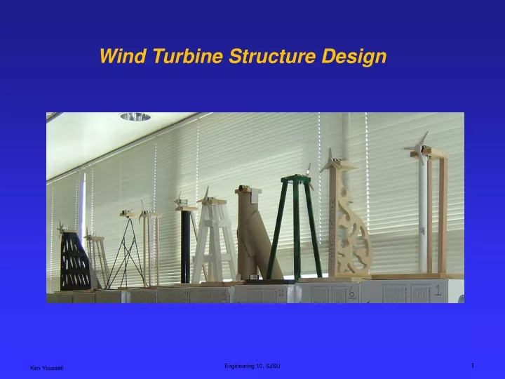
Wind Turbine Structure Design Engineering 10, SJSU
Blade design • Do your research on rotor design: blade profile, blade number and angle of attack before going to the lab. • Finish modeling your blade during the lab next week • Make sure your blade is not too thin (less than 1.5 mm or 1/16 inch), round the sharp edges and emboss the hub with your section and group number, S10 G9. • Your lab instructor will collect the .stl and part files at the end of the lab period. Engineering 10, SJSU
Blade edges too thin, not rounded Blade with rounded edge Emboss Group and section # on the hub Blade with sharp edge Do not cover the hole in the hub First blade modeled with rounded edge, rounded edges did not copied when array command created the other two. Engineering 10, SJSU
Wind Turbine Structure The Goal (Design objective) The support structure should be optimized for weight and stiffness (deflection) Minimize weight, maximize stiffness (minimize deflection) Support Structure Engineering 10, SJSU
Lattice structure Hollow tube with guy wire Wind Turbine Structure Hollow tapered tube Engineering 10, SJSU
Structural support Tripod support Wind Turbine Structure Tube with guy wire and winch Engineering 10, SJSU
Harmful to birds and bats Engineering 10, SJSU
Wind Belt (50 W) 9600 KWh of energy annually Mariah Power's Windspire Magnetic Levitation wind-turbine Helical wind turbine Engineering 10, SJSU
Wind Turbine Structure World Trade Center in Bahrain Three giant wind turbine provides 15% of the power needed. Engineering 10, SJSU
Sunbathing on top of a wind turbine Sunbathing on top of a 200-ft wind turbine Engineering 10, SJSU
Support structure failure, New York. Stress at the base of the support tower exceeding the strength of the material Engineering 10, SJSU
Support structure failure, Denmark. Caused by high wind Engineering 10, SJSU
Blade failure, Illinois. Failure at the thin section of the blade Support structure failure, UK Lightning strike, Germany Engineering 10, SJSU
Balsa wood Cardboard PVC Pipe Engineering 10, SJSU
X Engineering 10, SJSU
Provided Motor (generator), 1” diameter You design Blades Top plate to support the motor (wood, 3.5x3.5 inch) Support structure Bottom plate (wood, 12x12 inch) Engineering 10, SJSU
Δx F F F = k (Δx) where k = spring constant Δx = spring stretch F = applied force Spring Stiffness Compression spring Tension spring Engineering 10, SJSU
Deflection is proportional to load, F = k (∆x) Slope of Load-Deflection curve: The “Stiffness” Stiffness (Spring) Load (N or lb) slope, k Deflection (mm or in.) Engineering 10, SJSU
F F L A F F End view δ L E is constant for a given material E (steel) =30 x 106 psi E (concrete) =3.4 x 10³ psi E (Al) =10 x 106 psi E (Kevlar, plastic) =19 x 103 psi Stiffness for components in tension-compression E (rubber) =100 psi Stiffness (Solid Bar) • Stiffness in tension and compression • Applied Forces F, length L, cross-sectional area, A, and material property, E (Young’s modulus) Elongation (deflection) of the bar Engineering 10, SJSU
Deflection of a Cantilever Beam Support F = force L = length Y = deflection = FL3 / 3EI Fixed end Fixed end Mathematically, the area moment of inertia appears in the denominator of the deflection equation, therefore; The higher the area moment of inertia, the less a structure deflects (higher stiffness) Concept of Area Moment of Inertia Wind Engineering 10, SJSU
Wind Turbine Tower Stiffness Testing Dial indicator to measure deflection Pulley weights Engineering 10, SJSU
Note: Intercept = 0 Tower Stiffness Stiffness Force = .6364(deflection) Default is: • first column plots on x axis • second column plots on y axis Engineering 10, SJSU
Concept of Area Moment of Inertia The Area Moment of Inertia is an important parameter in determine the state of stress in a part (component, structure), the resistance to bending and buckling, and the amount of deflection in a beam. The area moment of inertia allows you to tell how stiff a structure is. The Area Moment of Inertia, I, is a term used to describe the capacity of a cross-section (profile) to resist bending. It is always considered with respect to a reference axis, in thexor y direction. It is a mathematical property of a section concerned with a surface area and how that area is distributed about the reference axis. The reference axis is usually a centroidal axis. Y = deflection = FL3 / 3EI Engineering 10, SJSU
Maximum distance of 4 inch to the centroid I2 Same load and location 2 2 x 8 beam Moment of Inertia – Comparison Y = deflection = FL3 / 3EI 1 Load 4” 2 x 8 beam centroidal axis I1 1” 2” Maximum distance of 1 inch to the centroidal axis Stiffer beam I2 > I1 , orientation 2 deflects less Engineering 10, SJSU
I-Beam and C-Channel Engineering 10, SJSU
Mathematical Equation for Area Moment of Inertia Ixx = ∑ (Ai) (yi)2 = A1(y1)2 + A2(y2)2 + …..An(yn)2 A (total area) = A1 + A2 + ……..An Area, A A2 A1 y2 y1 X X Engineering 10, SJSU
Round hollow section do di (d)4 [(do)4 – (di)4] I = I = 64 64 Rectangular solid section Rectangular hollow section 1 1 1 I = I = I = 12 12 12 b h=2 bh3 1 h H bh3 BH3 - b=8 12 B b hb3 h Moment of Inertia Equations for Selected Profiles d Round solid section Engineering 10, SJSU
Now, consider a hollow rectangular section 2.25 inch wide by 1.25 high by .125 thick. B = 2.25, H = 1.25 b = 2.0, h = 1.0 I = (1/12)(2.25)(1.25)3 – (1/12)(2)(1)3= .3662 -.1667 = .1995 Area = 2.25x1.25 – 2x1 = .8125 b h H B Compare the weight of the two parts (same material and length), so only the cross sectional areas need to be compared. (2 - .8125)/(2) = .6 = 60% lighter Example – Optimization for Weight & Stiffness Consider a solid rectangular section 2.0 inch wide by 1.0 high. 1.0 2.0 I = (1/12)bh3 = (1/12)(2)(1)3 = .1667 , Area = 2 (.1995 - .1667)/(.1667) x 100 = 20% less deflection So, for a slightly larger outside dimension section, 2.25x1.25 instead of 2 x 1, you can design a beam that is 20% stiffer and 60 % lighter Engineering 10, SJSU
Stiffness Comparisons for Different sections Stiffness = slope Rectangular Horizontal Square Box Rectangular Vertical Engineering 10, SJSU
Deflection of a Cantilever Beam Support F = force L = length Y = deflection = FL3 / 3EI Fixed end Material and Stiffness E = Elasticity Module, a measure of material deformation under a load. The higher the value of E, the less a structure deflects (higher stiffness) Engineering 10, SJSU
Ductile Steel (low carbon) Sy – yield strength Su – fracture strength σ (stress) = Load / Area ε (strain) = (change in length) / (original length) Material Strength Standard Tensile Test Standard Specimen Engineering 10 - SJSU
Yield Strength (Sy) • – the highest stress a material can withstand and still return exactly to its original size when unloaded. Ultimate Strength (Su) • - the greatest stress a material can withstand, fracture stress. Modulus of elasticity (E) • - the slope of the straight portion of the stress-strain curve. Ductility • - the extent of plastic deformation that a material undergoes before fracture, measured as a percent elongation of a material. % elongation = (final length, at fracture – original length) / original length Resilience • - the capacity of a material to absorb energy within the elastic zone (area under the stress-strain curve in the elastic zone) Toughness • - the total capacity of a material to absorb energy without fracture (total area under the stress-strain curve) Common Mechanical Properties Engineering 10 - SJSU
Modules of Elasticity (E) of Materials Steel is 3 times stiffer than Aluminum and 100 times stiffer than Plastics. E Engineering 10, SJSU
Density of Materials Steel Plastic is 7 times lighter than steel and 3 times lighter than aluminum. Aluminums Plastics Engineering 10, SJSU
Stiffness Testing Apparatus Successful testers Engineering 10, SJSU