
Cloud Networking Basics: Hub, Switch, IP, and ARP
E N D
Presentation Transcript
No Connection • Single user • No connection • Very secure
Connection • Two users • Crossover cable • Full duplex • Transmit and receiveat the same time • OSI layer 1 – Physical • Transmission of bits 100010100101010
Hub • Two or more users • A single network segment • Straight cables • OSI layer 1 – Physical • Transmission of bits • Hub • Amplifies signal • Broadcasts input on alloutputs • Clients reject inputs not for them • Half duplex – transmit or receive • Poor performance 101001 101001 101001 101001
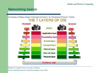
MAC (Media Access Control) Addressing • Uniquely identifies a network interface controller (NIC) • MAC addresses are used as a network address for Ethernet and Wi-Fi • Addresses are assigned by the manufacturer and stored in the NIC’s read-only memory or firmware • It is a 48-bit address for 281,474,976,710,656 possible MAC addresses (normally shown as 6 octets)ether 4a:00:02:00:ca:e0 (from ifconfig) • ipconfig or ifconfig commands show the MAC address
Packets and frames • A MAC address allows data to be directed to a specific device • The data segment is called a frame
Switch • Two or more users • A single network segment • Straight cables • OSI layer 2 – Data Link • Transmission of packets • Switch • Amplifies signal • Directs inputs to correct outputs • Full duplex • Best performance • Error checking 111011 101001 101001 111011
Switch operation • Works on the Layer 2 Header • Uses the source and destination MAC addresses to make its forwarding decisions. • MAC Address Table • maps the switch’s portsto MAC addresses • the source address and the port a frame was received on are entered in the MAC Address Table. • as each connected device sends a frame the table gets fully populated • the table is then used to forward frames to their intended destination
Local Area Network • When the area covered is small, such as an office, this is known as a Local Area Network (LAN) • Devices connected to the switches are called Hosts • The hosts are typically clients, servers or LAN attached peripherals, such as printers • A LAN can be wired or wireless • Switches can be cascaded to increase the number of hosts
Increasing the number of hosts • Adding switches is inefficient(inactive hosts are flushed from the MAC address table after 300s) • Adding hosts increases traffic congestion on the LAN(more collisions and failed transmissions) • Adding hosts means increased processing loads • The solution is to create additional physical networks
IP addresses • A MAC address is physical, it allows packets to be delivered from one NIC to another (hop to hop) • IP addresses are logical and allow delivery of packets across networks (from end to end) • IP addresses work at OSI layer 3 – Network • An address is a 32 bit binary number represented as 4 octets • E.g. 192.168.1.123 (IP v4) • Destination and source IP addresses are added to the data payload of the ethernet packet
Two networks 192.168.1.9 X R1 NIC R2 NIC A B Router 192.168.2.7 192.168.1.12
ARP Address Resolution Protocol • Used to find the MAC address for a given IP • Host A (192.168.1.12) needs to send to Host B (192.168.2.7) • It knows 192.168.2.7 is in a different network • It has a default gateway of 192.168.1.1 (the router) • It sends a broadcast ARP message (MAC ff:ff:ff:ff:ff:ff) for 192.168.1.1 (this goes to all hosts on the network) • Only the router replies with its Mac and IP addresses • Host A updates its ARP table • Sends packet to 192.168.2.7 with router MAC address
Router Table In Host A (192.168.1.12) • Contains a 0.0.0.0 entry which points to the default gateway 192.168.1.1 • Contains other IP addresses on its own network and the address of its own NIC • If sending to Host X it will look in the table and send directly • If sending to Host B (192.168.2.7) will find 0.0.0.0 as the closest match in the table and send to the gateway
Router’s Table • Contains a list of IP addresses and interfaces • If sending to 192.168.1.n will forward via R1 NIC • If sending to 192.168.2.n will forward via R2 NIC/24 refers indirectly to the number of hosts on the networkand is covered in subnetting (not in the BCS Cloud syllabus)
Windows Network Utilities • Ping • Tests connectivity • ping 192.168.2.7 • ARP • Shows MAC addresses for IP addresses
IP addresses • IP address classes • Class D is used for multicast (224-239) • Class E is experimental (240-255) • One class A address is worth 16M hosts • Therefore a way is needed to allocate significantly more hosts than are available
Private IP addresses • Address ranges allocated as private, therefore not permissible onto the general internet. • So, an organisation can have one outward facing IP address and up to 16M hosts inside • This is done using network address translation (explained later)
Setting IP addresses • Assume a small system with 192.168.1.n addresses • Static addresses are set on the device • Dynamic addresses are leased by a DHCP server
DHCP Dynamic Host Configuration Protocol • Host sends a discovery request (255.255.255.255) for a DHCP server • Server responds with a lease offer of an IP address, gateway address, duration and DNS server address (see later for DNS) • Host responds with a request to accept the offered lease • Server acknowledges the request • Host configures its network interface with the agreed parameters
DHCP Windows Configuration Static Dynamic
Recap • Hosts have MAC and IP addresses • They can communicate in the same network using switches and MAC addressing • To communicate between networks they use routers and IP addresses • Private IP addresses allow duplicate usage in different organisations, but are not allowed on the internet • IP addresses can be manually configured or obtained by DHCP
Internet connection • Connection to the ISP • ADSL • Cable • Satellite • Cellular • Leased line • ISP supplies: • IP address via DHCP • DNS address
ISP IP addresses • An ISP will allocate an IP address from a range it owns • These IP addresses are unique on the internet • Gloucester College IP address is 212.219.57.69 • All internet traffic to and from Gloucester College is via the IP address 212.219.57.69 • Internal IP addresses at the college will be from the private IP addresses ranges • How does traffic for a private IP address get to the right host?
Network and port address translation (NAT and PAT) • Implemented in the router • Allows many hosts on the internal network to connect via one public IP address • Allows many applications on one host to communicate with many services in the cloud • Uses IP and port numbers
Ports • An IP address and a port address make up a socket • Eg 212.219.57.69:80 (Gloucester college HTTP port) • An application, service or process uses the socket to send and receive data via the network – OSI Layer 4 Transport • The operating system • transmits the data from all application ports on to the network • directs received packets to the matching IP address and port number
Port allocation • Well known ports 0-1023 • Examples • 21 FTP • 25 SMTP • 80 HTTP • 110 POP3 • 443 HTTPS • Registered ports 1024-49151 • Dynamic ports 49152-65535
Browser request Host inserts random source port number Router translates internal network IP address to the external network address and port Router updates translate table and records port numbers
Server response Server puts source address from received packet into destination address of outbound packet Router translates external network IP address to the internal network address and port Host receives packet and OS directs to correct application
Domain Name System • Translates domain names to IP addresses • A host will query a domain name server (address from DHCP) with the domain name (eg www.techrepublic.com) • DNS server returns the IP address • Windows command: nslookup
Recap • Internal networks connect to the internet via ISP • The ISP allocates an IP address • Network address translation (NAT) allows private IP addressing • Port address translation (PAT) allows multiple applications to connect to cloud services • DNS allows memorable names to be used for cloud resources