Cadence tools
Cadence tools. Brandon Rumberg. Tools to cover. Creating piecewise linear (PWL) files OCEAN scripts Verilog-A. Why use PWL files?. Creating arbitrary waveforms in Cadence is tedious & changes are difficult. Piecewise linear source. Combining sources. PWLF Source.

Cadence tools
E N D
Presentation Transcript
Cadence tools Brandon Rumberg
Tools to cover • Creating piecewise linear (PWL) files • OCEAN scripts • Verilog-A
Why use PWL files? • Creating arbitrary waveforms in Cadence is tedious & changes are difficult Piecewise linear source Combining sources
PWLF Source • PWLF sources read from a piecewise linear file • ‘vpwlf’ in ‘analogLib’ library • The only necessary parameter is the file path/name Note: I’ve had trouble with the PWLF sources in the ‘NCSU_Analog_Parts’ library. They seem to have trouble finding the PWL file at times. So I recommend using the sources in ‘analogLib’
When PWL files are useful • Testing a circuit with a realistic input acquired from elsewhere • Such as a speech recording • Testing chip-level configuration logic • Such as a serial interface that controls parameters/connections within the chip • You can reuse these files to simplify post-fab testing • Performing a sequence of operations in one transient simulation • Particularly when the result of one operation affects the next operation
PWL files Time Value 0.00000000e+00 1.50000000e+00 1.17200000e-03 1.50000000e+00 1.17300000e-03 1.50000000e+00 1.27200000e-03 1.50000000e+00 1.27300000e-03 1.50000000e+00 3.35900000e-03 1.50000000e+00 3.36900000e-03 5.10000000e+00 4.36900000e-03 5.10000000e+00 4.37900000e-03 5.10000000e+00 1.54379000e-01 5.10000000e+00 • PWL files are text files with rows of time/value pairs • ‘Time’ and ‘Value’ are separated by a space • Each pair is on a separate line • Such files can easily be generated with • Matlab/Octave • Excel (save as txt file)
Generating PWL files • Create matrix with ‘time’ in the first column and ‘value’ in the second column • Save using save -ascii <filename> <matrix> • The file extension is arbitrary
Notes about PWLF • Cadence seems to read the PWL file at the instance that the schematic is saved • So if you generate a new PWL file, then you need to resave your schematic before starting a new simulation
Tips for generating PWL files T tr T tr • Keep in mind that PWL will be interpreted by connecting the dots • To simplify the creation of a bitstream • Define the hold (T) and rise/fall times (tr), then • Write a function that turns a string of bits into the desired waveform To create a step, you need to specify the point before the step
Tools to cover • Creating piecewise linear (PWL) files • OCEAN scripts • Verilog-A
OCEAN scripts • OCEAN is a simulator scripting language included in Cadence • Can be thought of as • Parametric sweeps on steroids, or • A cross between Matlab and a simulator • OCEAN • Exposes all simulator, graph, and calculator functions • Includes standard programming language functionality • File I/O • for/while loops • if/else branching • User-defined functions (called ‘procedures’) • Lisp syntax
An OCEAN of possibility • Circuit comparison • Create one OCEAN testbench and then automatically swap in/out different netlists • Algorithmic circuit tuning • Rather than using parametric sweeps, create an OCEAN script that automatically tunes the circuit • Parameter extraction • Have OCEAN extract the important circuit performance parameters and save them in a file
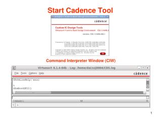
Creating an OCEAN script • The easiest way to get started is to set up an initial simulation in the Virtuoso environment, then ‘Session-Save Script’
Sample OCEAN script • Edit the script with a regular text editor • You can run the script using a different circuit by changing the path in design( ) Analysis Design variables Simulate and results
Running an OCEAN script • You can start ocean by typing ocean at the command line • Then by typing load(“<script>.ocn”) • To avoid retyping full commands, use • !<first letters of command><Enter> • e.g. !l<Enter> will rerun the last script
Modifying an OCEAN script • Use simulation result to calculate capacitor value that gives -20dB at high frequency Define design variables as variables so we can work with them Run first with arbitrary starting values Calculate high-frequency gain using standard calculator functions Calculate capacitor scaling to achieve target gain of -20dB (note that exponentials are done with **, not ^) Change the capacitor value based on the results Resimulate
Tools to cover • Creating piecewise linear (PWL) files • OCEAN scripts • Verilog-A
Verilog-A • A modeling language for analog simulation • Uses for Verilog-A • Replace transistor-level circuits • Simulate top-level before all circuits are finished • Evaluate top-level impact of circuit nonidealities • Speed up simulation • Modeling non-standard circuit elements
Creating a Verilog-A cell • Create a cell as normal, but choose ‘VerilogA-Editor’ for the tool • This creates and opens a Verilog template Note: You can change the default text editor by typing editor=“<editor name>” in the icfb window The default is vi. You may want to change to nedit for a more conventional text editor.
Insert your Verilog-A code Input/output terminals Parameters can be defined Define component operation
Symbol Creation & Compilation • When you close the editor window, you will be asked if you want to create a symbol for you Verilog-A code • Select ‘yes’ so that it will automatically generate your pins • The code is automatically compiled when you compile • If there is a syntax error you will receive a notification • Next is the symbol generation dialog box shown to the write • Create symbol as usual