GBT Project Status
GBT Project Status. Paulo Moreira CERN 08 June 2012. GBT Project. Sophie Baron Sandro Bonacini Pedro Cardoso Jorgen Christiansen Ozgur Cobanoglu Federico Faccio Rui Francisco Tullio Grassi Ping Gui Kostas Kloukinas Alessandro Marchioro Giovanni Mazza Mohsine Menouni

GBT Project Status
E N D
Presentation Transcript
GBT Project Status Paulo Moreira CERN 08 June 2012 GBT Project Status
GBT Project • Sophie Baron • Sandro Bonacini • Pedro Cardoso • Jorgen Christiansen • Ozgur Cobanoglu • Federico Faccio • Rui Francisco • Tullio Grassi • Ping Gui • Kostas Kloukinas • Alessandro Marchioro • Giovanni Mazza • Mohsine Menouni • Paulo Moreira • Christian Paillard • Karolina Poltorak • David Porret • Angelo Rivetti • Filip Tavernier • Guoying Wu • Ken Wyllie GBT Project Status
Outline • The GBT system • GBLD • GBTIA • GBTX: • “New” features • Status • GBT-SCA • GBT Project Future GBT Project Status
GBT System External clock reference FEModule Clock[7:0] E – Port e-Link GBTX Phase - Shifter CLK Reference/xPLL E – Port FEModule E – Port ePLLRx GBTIA DEC/DSCR CDR E – Port data-down data-up Phase – Aligners + Ser/Des for E – Ports CLK Manager clock GBLD 80, 160 and 320 Mb/s ports SCR/ENC SER E – Port ePLLTx FEModule E – Port E – Port One 80 Mb/s port Control Logic Configuration (e-Fuses + reg-Bank) GBT – SCA JTAG I2C Slave I2C Master E – Port I2C (light) data JTAG Port I2C Port control clocks GBT Project Status
GBLD Status • GBLD V4 performs according to specs (+): • Modulator • Laser bias • Radiation hardness proven! • Successfully integrated in the versatile link transceiver: • VTRx451 • (F. Vasey presentation today) • The ASIC is production ready! • Chips currently available in small quantities: ≈ 120 chips • Small “production” run • August: ≈ 80 chips 4.8 Gb/s, pre-emphasis on Total jitter: ≈ 25 ps GBT Project Status
GBTIA Status • First version fabricated in 2008: • Fully functional • Performance according to specifications (+) • Radiation hardness proven! • New version fabricated in 2011: • New pad layout • Received Signal Strength Indication (RSSI) • To facilitate optical fiber/PIN-diode alignment. • Higher reversed bias voltage for the PIN-diode • Voltage regulator 2.5 V to 2.0 V • Tests results reveal performance similar to the first version • Chips currently available in small quantities: ≈ 240 chips (bare dye) • Small “production” run: • August 2012, ≈ 80 chips GBT Project Status
GBTX: New features • The GBTX now supports three frame types: • “GBT” Frame • “Wide Bus” Frame • “8B/10B” Frame • “Wide Bus” and “8B/10B”frames are only supported for the uplink • The downlink always uses the “GBT” frame. • “Wide Bus” Mode: • Uplink data scrambled • No FEC • User bandwidth: 4.48 Gb/s • “8B/10B” Mode • Downlink data 8B/10B encoded • No FEC • User bandwidth: 3.52 Gb/s GBTX Phase - Shifter CLK Reference/xPLL E – Port ePLLRx DEC/DSCR CDR E – Port Phase – Aligners + Ser/Des for E – Ports CLK Manager SCR/ENC SER E – Port ePLLTx E – Port Control Logic Configuration (e-Fuses + reg-Bank) JTAG I2C Slave I2C Master GBT Project Status
GBTX - Status • GBTX team currently hard working towards the: • 6th of August MOSIS submission • Layout work very close to completion • Mainly verification work left to be done! • Preparation of the test-setup currently running in parallel with the ASIC design • Forecast: • Submission: • 6th of August 2012 • Chips back from foundry: • November 2012 • Chips packaged • Feb 2013 • Prototypes available for distribution: • May 2013 GBT Project Status
GBTX - Package • Package: • 20 × 20 ball array • 0.8 mm pitch • Size: 17 mm × 17 mm • Package: • Manufactured by ASE: • Integrate the decoupling capacitors • Integrate the XTAL • Package development by ASE has already started GBT Project Status
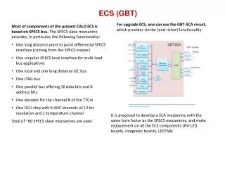
GBT – SCA Status • Dedicated to slow control functions • Interfaces with the GBTX using a dedicated E-link port • Standard e-Ports in the 80 Mb/s can be used as well • Communicates with the control room using a protocol carried (transparently) by the GBT • Implements multiple protocol busses and functions: • I2C, JTAG, PIA, etc… • Implements environment monitoring functions: • Temperature sensing • Multi-channel ADC • DAC • Specifications ready: • User Manual: https://espace.cern.ch/GBT-Project/GBT-SCA/Specification/GBT-SCA%20v5.0.docx • Technical Brief: https://espace.cern.ch/GBT-Project/GBT-SCA/Specification/GBT-SCA%20technical%20brief%20v0.2.docx • Under development • RTL code • DAC • ADC • Submission date • 8th of February 2012 • Chips packaged: • May 2013 • Prototypes available: • September 2013 GBT Project Status
GBT Project Future • LpGBT: Low power GBT chip set • Reduce the GBT chipset power consumption to ~ ¼ (~500 mW) • Two “SERDES” ASICs: • Simple SERDES with reduced functionality • Low pin count and footprint (targeting tracker developments) • Simple parallel port • Full GBTX functionality • General purpose • E-Links • High bandwidth capability (option under consideration): • Downlink 4.8 Gb/s (as in the GBTX) • Uplink two modes: 4.8 and 9.6 Gb/s • E-Links double the bandwidth in the 10 Gb/s mode • Technology: 65 nm CMOS • LpGBT – SerDes • LpGBTX • LpGBLD will be very likely kept in 130 nm CMOS • Serious development effort to start summer 2012 • Target: • LpGBT – SerDes prototypes in 2015 • LpGBTX prototypes in 2016 GBT Project Status
Backup Slides • Backup Slides • Backup Slides • Backup Slides • Backup Slides • Backup Slides • Backup Slides • Backup Slides • Backup Slides • Backup Slides • Backup Slides • Backup Slides • Backup Slides • Backup Slides • Backup Slides • Backup Slides • Backup Slides • Backup Slides • Backup Slides • Backup Slides • Backup Slides • Backup Slides • Backup Slides • Backup Slides • Backup Slides • Backup Slides • Backup Slides • Backup Slides • Backup Slides • Backup Slides • Backup Slides • Backup Slides • Backup Slides GBT Project Status
GBT Mode (For Up/Down-Links) 120 bits H(3:0) IC(1:0) EC(1:0) D(79:64) D(63:48) D(47:32) D(31:16) D(15:0) FEC(31:16) FEC(15:0) 4 bits 2 bits 2 bits 80 bits 32 bits G4 G3 G2 G1 G0 EC GBT Frame • 3 groups of 8 output e-Ports • 2 groups of 8 input/output e-Ports (operating as outputs) • 5 groups of 8 input e-Ports. • Number of data e-links (excluding EC e-Link): • 40 input (max @ 80 Mb/s) • 40 output (max @ 80 Mb/s) • One e-Port: • Fixed data rate 80 Mb/s Block Diagrams
e-Ports to Frame Mapping in the GBT Mode Uplink (GBT - Frame) Downlink (GBT - Frame) Block Diagrams
Wide Bus Mode (Valid only for the Up-Link) 120 bits 2 bits 2 bits 112 bits H(3:0) IC(1:0) EC(1:0) D(79:64) D(63:48) D(47:32) D(31:16) D(15:0) D(111:96) D(95:80) G4 G3 G2 G1 G0 G6 G5 EC Wide Bus Frame “Out of order” bit sequence for compatibility with the GBT frame • One e-Port: • Fixed data rate 80 Mb/s • 3 groups of 8 output e-Ports • 2 groups of 8 input/output e-Ports (operating as inputs) • 5 groups of 8 input e-Ports • Number of data e-links (excluding EC e-Link): • 56 input (max @ 80 Mb/s) • 24 output (max @ 80 Mb/s) Block Diagrams
e-Ports to Frame Mapping in the GBT in the Wide Bus Mode Uplink (Wide Bus Frame) Downlink (GBT - Frame) 16, 8 or 4 “Output” E-Links become inputs Shift order for the E-Link data inputs and outputs is MSB first Block Diagrams
8B/10B Mode (Valid only for the Up-Link) 5 groups of 8 E-ports 1 group of 4 E-ports G6 (not used) G5 (1/2) G4 G3 G2 G1 G0 8B/10B Frame 8B/10B 8B/10B 8B/10B 8B/10B 8B/10B 8B/10B 8B/10B 8B/10B 8B/10B 8B/10B 8B/10B 8B/10B • 3 groups of 8 output e-Ports • 1 group of 8 input/output e-Ports (operating as outputs) • 1/2 group of 8 input/output e-Ports (operating as 4 outputs) • 5 groups of 8 input e-Ports. • 1/2 group of 8 input/output e-Ports (operating as 4 inputs) • Number of data e-links (excluding EC e-Link): • 44 input (max @ 80 Mb/s) • 36 output (max @ 80 Mb/s) To maximize the use of e-Ports then group 5 has to be used 1/2 as inputs and the other 1/2 as outputs. So the termination Resistors for this group have to be controlled in two sets of 4 resistors. Block Diagrams
e-Ports to Frame Mapping in the GBT in the 8B/10B Mode Uplink (8B/10B frame) Downlink (GBT - frame) 4, 2 or 1 “Output” E-Links become inputs Block Diagrams