Download
1 / 10
100 likes | 171 Vues
Reduction of power converter size through increase of switching frequency. Increasing switching frequency reduces value and size of filter inductances and capacitances Up to a point, increasing switching frequency reduces transformer size

E N D
Reduction of power converter size through increase of switching frequency • Increasing switching frequency reduces value and size of filter inductances and capacitances • Up to a point, increasing switching frequency reduces transformer size • Increasing switching frequency increases switching loss: Psw = fsw ∆vds Qsw • Much R&D effort has been devoted to increasing the switching frequency and reducing the loss in high-density power supplies • Approaches to achieve these goals include use of resonant converters and soft switching techniques
4.3. Switching loss • Energy is lost during the semiconductor switching transitions, via several mechanisms: • Transistor switching times • Diode stored charge • Energy stored in device capacitances and parasitic inductances • Semiconductor devices are charge controlled • Time required to insert or remove the controlling charge determines switching times
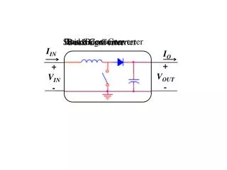
4.3.1. Transistor switchingwith clamped inductive load Buck converter example transistor turn-off transition Loss:
4.3.4. Efficiency vs. switching frequency Add up all of the energies lost during the switching transitions of one switching period: Average switching power loss is Total converter loss can be expressed as where Pfixed = fixed losses (independent of load and fsw) Pcond = conduction losses
Efficiency vs. switching frequency Switching losses are equal to the other converter losses at the critical frequency This can be taken as a rough upper limit on the switching frequency of a practical converter. For fsw > fcrit, the efficiency decreases rapidly with frequency.
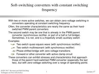
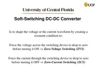
Soft switching:Zero-voltage and zero-current switching Soft switching can mitigate some of the mechanisms of switching loss and possibly reduce the generation of EMI Semiconductor devices are switched on or off at the zero crossing of their voltage or current waveforms Conduction sequence: D1–Q1–D2–Q2 Q1 is turned on during D1 conduction interval, without loss
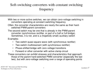
Soft switching in a PWM converterExample: forward converter with active clamp circuit Forward converter Switching transitions are resonant, remainder of switching period is not resonant Transistors operate with zero voltage switching Beware of patent issues
Analysis of resonant converters Series resonant dc-dc converter example • Complex! • Small ripple approximation is not valid • Need new approaches: • Sinusoidal approximation • State plane analysis
Outline of course • 1. Analysis of resonant converters using the sinusoidal approximation • Classical series, parallel, LCC, and other topologies • Sinusoidal model • Zero voltage and zero current switching • Resonant converter design techniques based on frequency response • 2. Sinusoidal analysis: small-signal ac behavior with frequency modulation • Spectra, beating, and envelope response • Phasor transform method • 3. State-plane analysis of resonant, quasi-resonant, and other soft-switching converters • Fundamentals of state-plane and averaged modeling of resonant circuits • Exact analysis of the series and parallel resonant dc-dc converters
Outline, p. 2 • 4. Resonant switch and related converters • Quasi-resonant topologies and their analysis via state-plane approach • Quasi-square wave converters • Zero voltage transition converter • Soft switching in forward and flyback converters • Multiresonant and class E converter • 5. Server systems, portable power, and green power issues • Modeling efficiency vs. load, origins of loss • Variable frequency approaches to improving light-load efficiency • DCM • Burst mode • Effects of parallel modules • DC transformers