Download
1 / 28
280 likes | 454 Vues
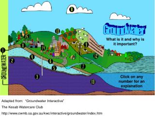
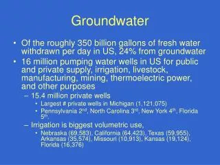
This guide elaborates on mechanised pumps used in groundwater pumping, highlighting different power sources such as electricity, diesel engines, photovoltaic systems, and wind-powered pumps. It explores various types of motorised pumps, including radial flow, axial flow, and submersible pumps, explaining their functions and operational principles. Additionally, it provides insights into positive displacement pumps and the efficiency of electric motors versus diesel engines, alongside key considerations for pump selection based on specific demands and applications.

E N D
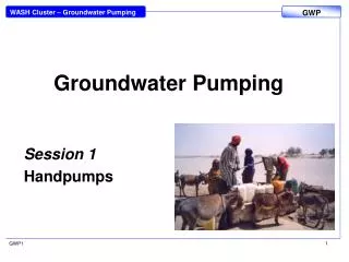
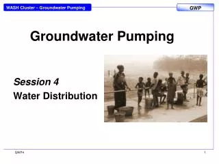
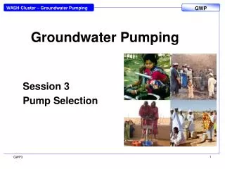
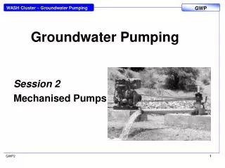
Groundwater Pumping Session 2 Mechanised Pumps 1 GWP2
They may be driven by: Electricity from the national grid, Diesel engine for direct drive Diesel engine for electricity generation Photovoltaic system Wind-powered pumps Power sources GWP2
Motorised Pumps • Pumps are machines designed to add energy to fluids. They typically do this by using a rotating element to push a fluid in one direction. • Rotodynamic pumps generate flow by using one of three actions: radial flow, mixed flow, and axial flow. • These classifications do not rate the performance quality of the pump, they are merely groupings based upon the pump’s action. 4 GWP2
Motorised Pumps (Radial Flow) • Radial flow pumps are centrifugal pumps in which the pressure is developed wholly by centrifugal force. • Radial flow pumps consist a rotating impeller and stationary casing (volute or solid). The impeller produces liquid velocity and the casing forces the liquid to discharge from the pump converting velocity to pressure. • Centrifugal pumps to produce continuous flows at high pressure. 5 GWP2
Motorised Pumps (Axial Flow) • In mixed flow pumps, the pressure is developed partly by centrifugal force and partly by the lift of the vanes of the impeller on the liquid. • Axial flow centrifugal pumps develop pressure by the propelling or lifting action of the vanes of the impeller on the liquid. • An axial flow essentially consists of a propeller in a pipe. The propeller can be driven directly by a sealed motor in the pipe or mounted to the pipe from the outside by a drive shaft that pierces the pipe. 6 6 GWP2
Submersible Pumps • Centrifugal Pumps are rotodynamic pumps, which convert mechanical energy into hydraulic energy by centripetal force on the liquid. A rotating impeller increases the velocity of the fluid. The vanes in the casing of the pump then convert this amplified velocity into a rise in pressure. The pumps usually have multiple impellers. The selection of the correct size of the pump for its intended duty point is important. Energy is wasted if the pumps are operated far away from the optimal running point. 7 7 GWP2
Submersible Pumps • The main parts of a submersible pump are: • Electric motor hermetically enclosed in a stainless steel sleeve, • Pump body either a centrifugal pump or a positive displacement pump • Rising main of GI or stainless steel pipes connected with sockets or PVC-HI hose. If a hose is used, the motor with connected pump body has to be hung from the top of the well by a stainless steel cable, • Electrical cable for connecting the motor to the starting panel (power source), • Starting panel • Various sizes of submersible pumps are available, which can be installed in casings of Ø3”, 4”, 6”, 8”, 10” and 12”. 8 GWP2
Positive displacement pump • Progressive cavity pumps • Water moves by trapping a fixed amount of fluid and forcing that trapped volume into the discharge pipe. • Pump is a single helix rotor inserted into a double helix stator. • This forms pockets of water which are lifted from the bottom to the top • Produces a constant flow • Small diameter pumps for boreholes are considerably more efficient than centrifugal pumps. • Progressive cavity pumps have high starting torque which is important if using solar systems 9 9 GWP2
AC mains power • Electric motors are generally available from the smallest size of 100-200W. They run on a fixed speed depending on the frequency (1500rpm at 50 Hz or 1800rpm at 60Hz). Energy efficiency is between 75% for small motors to 90% for bigger size motors. • Long distances from grid to the pump site require high investment in the power line. Mains electricity is normally supplied as single phase current at either 220 Volt and 50 Hz frequency (Europe, Africa, Asia) or at 110V and 60Hz (America). For high power connections over 10KW nearly always 3-phase power is supplied at a voltage of 380V. 10 GWP2
Internal combustion engines • Petrol engines are less common because the highly flammable fuel is difficult to handle and they are not as reliable and efficient as diesel. • Diesel engines for stationary applications run at about 1,200 to 1,400 rpm and their efficiency is about 30% (i.e. the fuel consumption is about 200-300 g/kWh or 0.25 – 0.4 lt/kWh). • Engines require regular maintenance, which necessitates often a full-time operator. And the logistics to ensure that enough fuel and lubricants are always available need to be sorted out. • Diesel fuel is more expensive than electricity from the grid. • Diesel generators are used in places without connection to the power grid or as emergency power-supply if the grid fails. These generators are widely used for not only emergency power, but also many have a secondary function for providing back up power to utility grids. Diesel Generator (Skat) Petrol Generator (Briggs and Stratton) 11 GWP2
Pump selection to meet demand When water is pumped to a higher elevation the pumping effort is the total head plus the friction head loss in the pipeline. The friction head loss for a given flow rate can be calculated for any chosen pipe diameter. Smaller pipes create higher losses than bigger pipes because the water speed is greater. The pump has to be chosen that is able to produce the required flow and pressure. The daily water demand in a community area will vary during the year due to seasonal pattern of the climate, the work situation, cultural or religious occasions 12
Pump power Pw = Qρgh Where: Pw= Water power Q = flow rate of water (m3/s) ρ= density of water (≈1000kg/m3) g = 9.8m/s2 h = operating pressure head Required input power = Pw/η Where η = overall efficiency
Sizing a pump • Draw system curve for range of flows, including the required flow (use table given as handout) • Select a pump which matches the duty required and obtain the characteristic curves • Superimpose the two curves to find the operating point • Check it gives you the required flow rate
Adjusting your pump Ideally the operating pump will correspond as closely as possible to the required flow rate. Otherwise you can alter the speed of the pump to achieve this but: Flow – varies with speed Head – varies with (speed)2 Power – varies with (speed)3 So varying the speed will greatly increase the power demand.
Sphere standards: max 500 people/handpump – assume need to use max Daily necessary is 15 l/person and say head is 30m. 17 GWP2
Solar One slide explaining PVs A photovoltaic module is a packaged interconnected assembly of photovoltaic cells, also known as solar cells. Current is created when light falls onto the active surface. mono-crystalline silicon, multi-crystalline silicon, and amorphous silicon. New, non-silicon types such as cadmium telluride (CdTe) and Copper Indium Disellenide (CIS) have recently become available too. 19 GWP2
Solar 20 GWP2
Sizing Photovoltaic System The mean daily water demand and the mean daily solar irradiation during the least sunny month need to be determined as the starting point for sizing a solar pump. The diagram provides a quick indication of power requirements. It should be noted that the result is only an estimate and the graph should not be used for final sizing of the system Session Name here 21 21 GWP2
Simplified method for sizing Fraenkel and Thake give a simplified method of calculating the size of a solar system in their book Water Lifting Devices. The method provided here is an adaptation of their method that facilitates a ‘rough and ready’ calculation of the solar array. Sources such as the World Meteorological Organization publish irradiation figures for the whole world. Maps that cover large areas or whole regions can be used to make a reasonably accurate judgement of the irradiation for a particular location. Peter Fraenkel and Jeremy Thake, Water Lifting Devices: A Handbook for Users and Choosers (Food and Agriculture Organization, 2006). 22 22 GWP2
23 23 GWP2
To get a fairly accurate idea of the size and cost of a photovoltaic array it is necessary to know at least the following parameters: • Water consumption per capita per day • Total no. of households • Persons per household • Total population • Yield of water source (m3/day) • Distance to source • Distance from source to tank • Static water table • Expected dynamic water table • Elevation from source to tank • Total pumping head 24 24 GWP2
Motorised Pumps • There are three main types of motorised pumps that are suitable to be installed in boreholes: • Submersible Pumps • Line Shaft Pumps • Jet Pumps • The standard power sources possible for the three pump types mentioned above are: • Electric AC mains • Diesel engines • Petrol engines her. • Solar powered Pumps • Wind powered Pumps 26 GWP2
Line Shaft Pumps • Line Shaft Pumps have the driving element (motor) above ground; and the pumping element is at the bottom of the well. A “Line Shaft” is used to connect the motor with the pumping element. • The speed of the motor is directly applied to the pumping element by the line shaft. Gearboxes or V-belt drives might be used for adjusting the speed. Various motor types can be used to drive the pumping element (diesel engine, petrol engine, electric motor etc.). • The pumping element can vary too, but mostly used are: • Vertical turbine pumps similar to the submersible pumps, • Positive displacement unit, progressive cavity pumps (Mono). 27 27 GWP2
Jet Pumps A Jet Pump is an impeller-diffuser pump. About half of the drawn water is split in the diffuser and sent back to the well with high pressure through the pressure pipe. At the end of the pressure pipe, the water is accelerated through the cone shaped nozzle and guided through the mixing chamber with high speed. A pressure drop in the mixing chamber sucks in water from the ejector body and intake. The water goes up the return pipe and through the impeller into the diffuser, where one part is sent back to the jet nozzle and the other part is directed into the delivery pipe. Jet Pumps are relatively inefficient but can tolerate a wide range of operating conditions, including abrasive fluids such as water with high sand contents. 28 28 GWP2