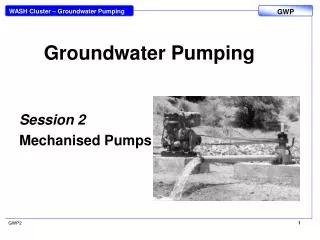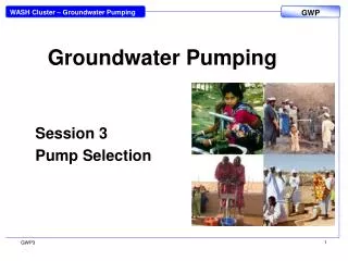
Groundwater Pumping
Groundwater Pumping. Session 1 Handpumps. Pumping principles. Creating a velocity head Water can be propelled to a high speed. The momentum produced can be used either to create a pressure or a flow. Propeller Pumps, Centrifugal Pumps, Rebound Inertia Pumps, Jet Pumps. 3. GWP1.

Groundwater Pumping
E N D
Presentation Transcript
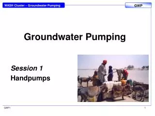
Groundwater Pumping Session 1 Handpumps GWP1
Pumping principles Creating a velocity head Water can be propelled to a high speed. The momentum produced can be used either to create a pressure or a flow. Propeller Pumps, Centrifugal Pumps, Rebound Inertia Pumps, Jet Pumps. 3 GWP1
Pumping principles Using the buoyancy of a gas Air that is blown into water bubbles upward. It will lift a proportion of the water that it flows through. http://www.koenderswindmills.com/Koenders_Windmills_AirDr.html 4 GWP1
Pumping principles Gravity Energy of a media (water) that flows downward under gravity is used to lift water. Siphons http://www.asseenontvguys.com/liquid-transfer-pump.aspx 5 GWP1
Pumping principles Displacement Water cannot be compressed so it is pushed or displaced. Piston Pumps, Progressive Cavity Pumps and Diaphragm Pumps GWP1
Displacement - Reciprocating handpumps During the downstroke the atmospheric pressure acts equally on all water surfaces. The foot valve stays closed, preventing water from being pushed back into the well. The piston presses down onto the water until the non-return piston valve opens, allowing water to flow through the piston. During the upstroke the weight of the water column causes the piston valve to close. The water above the piston rises up in the rising main, flowing out by the spout. A vacuum is created below the piston, the atmospheric pressure pushes water into the cylinder. GWP1
Displacement - Suction pumps • The cylinder is above the water table The rising main extends below the water table. • The atmospheric pressure forces the water into the area of low pressure underneath the piston. • The theoretical limit to which the atmospheric pressure can push up water is 10 metres. In practice, suction pumps can be used to lift water up to about 7 or 8 metres. • The pump needs to be primed before it can be operated • Maintenance is easy as the cylinder is accessible above ground 8 GWP1
Displacement - Direct action pumps • Direct action handpump have a T-handle directly connected to the pump rod and the piston. • The pump rods are sealed airtight, thus buoyant which reduces the force needed on the up-stroke. They deliver water during up- and down-stroke. • Direct action pumps are normally corrosion resistant, and very easy to handle by the community. GWP1
Displacement - Lever action pumps • When the water has to be drawn from deeper levels, pumping becomes heavier. To gain a mechanical advantage levers are used to operate the pump. • Lever action pumps consist of: • above-ground components like pump head, pump stand and handle • down-the-hole components like rising main, pump rods with plunger, cylinder and foot valve. GWP1
Rope pumps • The Rope Pump is not defined with a specific design but a concept • Small workshops produce different rope pump designs, adapted to their local conditions, sell the pumps directly to the users. • A pulley wheel (made of a car tyre) pulls the rope with the attached pistons through the rising main pipe. • The pistons transport the water upwards to the spout. GWP1
Progressive cavity pumps • Progressive cavity pumps can be used in small diameter boreholes. • The pump has a rotor made to a high finish inserted into a rubber double helix stator. • When the rotor is turned the water will pushed upwards and discharged into the rising main. • Progressive cavity pumps need to be driven at a relatively high speed; therefore, handpumps are often fitted with a gearbox. This makes this type of pump relatively complicated and costly. 12 GWP1
Diaphragm Pumps • Diaphragm Pumps use a flexible diaphragm, which is expanded and contracted to displace water. • They have no heavy mechanical parts below ground. • The high quality diaphragms are costly • The overall efficiency is relatively low because of the energy needed to expand the diaphragm on every stroke. 13 13 GWP1
Example Progressive Cavity Pumps GWP1