Download
1 / 28
280 likes | 714 Vues
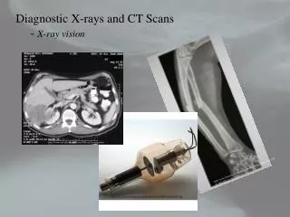
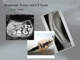
Diagnostic X-rays and CT Scans - X-ray vision. http://www.uab.edu/surgonc/cases/GI/case2/ctscanof.htm. http://www.bjwinslow.com/albums/medicalcharts/broken_arm_radius_and_ulna_x_ray_10.jpg. http://www.museumboerhaave.nl/AAcollection/AAJPEGS/M22/9955.jpg. Diagnostic X-rays and CT Scans

E N D
Diagnostic X-rays and CT Scans - X-ray vision http://www.uab.edu/surgonc/cases/GI/case2/ctscanof.htm http://www.bjwinslow.com/albums/medicalcharts/broken_arm_radius_and_ulna_x_ray_10.jpg http://www.museumboerhaave.nl/AAcollection/AAJPEGS/M22/9955.jpg
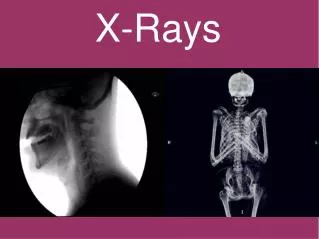
Diagnostic X-rays and CT Scans - motivation and outline • X-rays have been known for over 110 years. • X-rays are the most utilized modern medicinal technique. • “X-rays” in the colloquial sense are actually radiographs – intensity mappings of the shadows created when an x-ray beam passes through materials. • The x-rays are absorbed as they pass through tissue and bone and what emerges is displayed on a film or stored digitally (called a CT or computed tomography scan) and used to reconstruct an image of the object that absorbed the x-rays. • One limitation of film x-rays is their lack of depth information. • A CT or computed tomography scan can distinguish the different absorbing layers since the images are stored electronically and can be processed separately. • Diagnostic x-rays are a type of ionizing radiation and there are inherent risks associated with an x-ray scan.
Diagnostic X-rays and CT Scans - motivation and outline • Even though x-rays produce ionizing radiation, the risks seem to be negligible, with small doses of radiation, compared to the medical benefits. • We’ll investigate x-ray production and then use it to produce a radiograph. • In order to produce a radiograph we need to determine how the x-rays interact with body tissues and bones. • Then we will see how organs, which normally cannot be imaged with x-rays, can be imaged by using a suitable contrast medium. • Then we’ll investigate computed tomography and see how to digitally reconstruct x-ray images. • Two applications will be considered, mammography and osteoporosis.
Diagnostic X-rays and CT Scans - Production of x-rays • To produce these electrons the filament is heated by passing an electric current through the tungsten wire and the electrons are thermally emitted. • Free electrons are produced at a tungsten filament and these free electrons are accelerated to the right by an electric field is generated between the cathode (-) to the anode (+) by applying a potential difference across the cathode/anode. • The anode geometry could be fixed or rotatable. Here we have a rotatable anode. • The material that the anode is constructed from will determine the type of x-rays that are generated and their energies. • The kinetic energy of the electron is given by qDV and the energies are usually several keV’s. • Most of the electrons energy goes to heating the anode, but some will produce x-rays. http://openlearn.open.ac.uk/file.php/3318/S809_1_004i.jpg
Diagnostic X-rays and CT Scans - Production of x-rays • The heat has to be removed or the x-ray tube will suffer damage. • - usually the anode will melt. • Usually these x-ray units are water cooled. • A rotating anode spreads out the heat so that it can be dissipated over a larger area. • There are two mechanisms to produce x-rays from the rotating anode. • Bremsstrahlung – or braking radiation • The electrons are slowed down, or decelerated, and the accelerating charge produces a continuous emission of radiation. • This is exactly how a light bulb works, except the electron energies are much less. • electrical interactions (forces) between the electrons and the atomic nucleus of the anode decelerate the electrons.
Diagnostic X-rays and CT Scans - Production of x-rays • Diagram of the Bremmstrahlung process. • The electrons interaction is electromagnetic in nature. • As the electron decelerates radiation is produced all along its path. • Depending on how the electron interacts with the nucleus will determine its energy. http://www.astro.wisc.edu/~bank/index.html • Glancing collisions produce low energy x-rays while “head-on” collisions convert almost all of the energy of the electron into an x-ray.
Diagnostic X-rays and CT Scans - Production of x-rays • The second mechanism for x-ray production is called PIXE or particle induced x-ray emission. • The high energy electron can knock out an inner shell electron and this creates a vacancy in the inner shell. • In order to conserve energy an electron from a higher orbital will transition to the inner orbital, with an emission of a photon in the x-ray portion of the EM spectrum. • Of course, you don’t have to use electrons – you could use protons. This is what’s done using the accelerator in the basement. • The x-rays produced are characteristic of the anode material. http://www.helmholtz-muenchen.de/uploads/pics/pixe_2_textmedium.jpeg
Diagnostic X-rays and CT Scans - The characteristic x-ray spectrum • The total spectrum is the sum of the contributions due to Bremmstrahlung and PIXE. • The incident electrons eject inner shell electrons from the target material and this produces characteristic x-rays with a given energy or wavelength. • In addition, those incident electrons that don’t eject inner shell electrons of the target material will however undergo glancing interactions and this produces the braking deceleration and this produces the continuum of background. • This is the emission spectrum for Cu and the energy of the photons determines the wavelength of the x-ray through http://www.msm.cam.ac.uk/doitpoms/tlplib/xray-diffraction/images/spectra.gif
Diagnostic X-rays and CT Scans - The characteristic x-ray spectrum • The characteristic x-ray energies are due to the transitions that the electron makes from the higher orbital to the lower orbital. • The two highest energy transitions are called the Ka and Kb, for the electron being ejected from the innermost shell, termed the K-shell. • The highest probability transition is the Ka and the lower probability transition is the Kb and these are seen by intensity in the emission spectrum. http://www.msm.cam.ac.uk/doitpoms/tlplib/xray-diffraction/images/spectra.gif
Diagnostic X-rays and CT Scans - The Interactions of X-rays and Matter • X-rays interact with matter in two ways • Photoelectric Effect • Compton Effect • These two effects are responsible for the absorption and scattering of x-rays and thus the ultimate quality of the radiograph. • The photoelectric effect dominates for x-rays with energies lower than about 25 keV. • The incoming x-ray photon interacts with inner shell electrons of usually light elements, say C, H, O or N that makes up soft tissues. • The inner shell electron can absorb ALL of this photon’s energy and the electron can be ejected. • Any excess energy (outside what it takes to unbind the electron) shows up as KE in the electron.
Diagnostic X-rays and CT Scans - The Interactions of X-rays and Matter • The photoelectron is free to travel throughout the body, but in general it only travels a small distance before its energy is reabsorbed. • The vacancy that was created by the production of a photoelectron is quickly filled by a higher orbital electron with an emission of an x-ray characteristic of the element that produced the photoelectron. • This x-ray photon can be produced in any random direction and is responsible for scattering in the x-ray beam. • The probability that an x-ray photon will • be absorbed or transmitted depends on the • elements in the absorbing material. • In fact, photoelectric absorption increases • with the cube of the atomic number. http://www.thermo.com/eThermo/CMA/Images/Various/151Image_15772.gif
Diagnostic X-rays and CT Scans - The Interactions of X-rays and Matter • The photoelectric effect also increases with decreasing photon energy, a consequence of the uncertainty principle. • This interaction produces, again, a photon with the same energy needed to remove the atom’s electron and this is in a random direction. • This lowers the intensity of, or attenuates the incident beam and produces ions in the body. • Most interactions of photons and bones and the ultimately the image receptor (say film) are photoelectric in nature. • Photoelectric events are usually viewed as an elastic collision. • These produce the shadows in the x-ray film. • High Z materials make for good shielding devices.
Diagnostic X-rays and CT Scans - The Interactions of X-rays and Matter • The other photon-electron interaction is the Compton Effect. • In the Compton effect, which can be viewed as an inelastic collision, the incident photon gives some of its energy to the electron in the atom with which it collides, but the photon is scattered. • The scattered photon has less energy (it transferred momentum to the electron) and this produces longer wavelength radiation in a perhaps different direction than the incident beam. • Here the interaction time is very short in accordance • with the uncertainty principle and the Compton • effect also attenuates the x-ray beam. • The electron recoils at a very high velocity. • Most interactions between x-rays and • soft tissues are Compton scattering events. http://illumin.usc.edu/_images/pictures/ii9_170_compton.gif
Diagnostic X-rays and CT Scans - The Interactions of X-rays and Matter The central theme of radiology X ray photons are removed from a beam and the energy is given to a medium by a two-stage process: 1. The photon first ionizes the medium’s atoms or molecules by either the Compton or photoelectric effects by a collision with an orbital electron and therefore is removed from the beam. 2. The result produces a high velocity photoelectron or Compton scattered electron which ionizes hundreds or thousands of other atoms or molecules and this produces a medium response, which is usually tissue damage.
Diagnostic X-rays and CT Scans - The Interactions of X-rays and Matter • There are functionally three categories of materials with which the x-rays interact. • 1. The soft tissues and bones in the body. • 2. The materials involved in detecting the radiation that passes through the body. • 3. The shielding. • These arise out of the interactions of the x-rays with the material in which they are propagating.
Diagnostic X-rays and CT Scans - The Interactions of X-rays and Matter - Photon Removal from the Beam • Photon-electron interactions (photoelectric or Compton effects) remove photons from the incident beam. • The number of photons removed depends on the material in which the photon is incident. • This produces the radiographic shadows in the detector material. • Compton scattered photons are usually useless for imaging since they won’t necessarily strike your detector. • The Compton scattered photons will either get absorbed and deposit energy in the body (which can produce chemical or cellular changes) or simply become background fog on your detector. • The absorption of photons by the photoelectric effect help to provide effective shielding sources such as lead. (In high Z materials the photoelectric effect dominates.)
Diagnostic X-rays and CT Scans - The Interactions of X-rays and Matter - Energy deposition in the material • Energy deposition in the body does not help the image formation process. • Could be bad for the body leading to cellular or chemical changes. • - how much is too much? • For the detector material, it is the subsequent ionization in the material that is used to form the image. • The high velocity photoelectrons or Compton scattered electrons ejected by the incident x-rays that make it through the body and into the material create an electrical or chemical signal that the detector can recognize. • For example, in a film the x-rays stimulate and excite a chemical emulsion to expose the film. In a silicon crystal detector, the x-ray creates electron-hole pairs and placing an electric field across the silicon crystal causes the electron-hole pairs to drift and this current is recorded as a measure of the x-ray energy.
Diagnostic X-rays and CT Scans - The Interactions of X-rays and Matter • The production of a radiograph • The x-ray tube generates the x-rays and the x-rays are produced and spread out through space. • A collimator is placed in the beam’s path and most x-rays get absorbed in the collimator. • A fraction get through and a narrow beam strikes the patient. • These x-rays are mostly absorbed by the body but about 1% make it out and are used to expose a film or to create electrical signals in a detector for image formation. Wolbarst, Physics of Radiology
Diagnostic X-rays and CT Scans - The Interactions of X-rays and Matter - X-ray Detectors • Radiological film: • The emulsion consists of a gelatin material containing an even distribution of the radiation-sensitive silver bromide crystals or grains. • The double emulsions essentially reduce exposure requirements to one-half that required for a single emulsion, but most radiography films have emulsion only on one side. • The interaction of the x-rays with the emulsion material (a cubic lattice of Ag+ and Br- ions) sensitizes (excites) the grains and during the development process this turns the grains black. • The grains not sensitized are removed during the development process. http://www.tpub.com/content/chemical-biological/TM-1-1500-335-23/css/TM-1-1500-335-23_528.htm
Diagnostic X-rays and CT Scans - The Interactions of X-rays and Matter - X-ray Detectors • The net result for film are regions of black (complete sensitization) and regions of various shades of grey. • The degree of sensitization depends on the energy of the incident x-ray. • To determine the energy of the ray on the film or detector we need to look at how materials absorb the x-rays. • Posterior rib fracture of the left 7th rib as well as lateral fractures of the 4th – 6th ribs Typically, this is part of violent shaking. The infant or young child is held very tightly around the chest and squeezed while being shaken. This compresses the ribs front to back and tends to break them next to their attachment to vertebrae and laterally where they are being literally almost folded in half. Therefore, lateral & posterior rib fractures are highly specific for abuse. The Child Abuse Referral and Education (CARE) Network of the Uniformed Services University of the Health Sciences http://rad.usuhs.mil/rad/home/peds/acutepostarrow.jpg
Diagnostic X-rays and CT Scans - The Interactions of X-rays and Matter - X-ray Detectors • A typical Si(Li) X-ray detector • An array of these form the basis for a CT scan. • These are actually lithium drifted silicon detectors – semiconductor devices. • The incident x-ray produces equal and opposite charge carriers that are separated by the application of an electric field. • The subsequent current pulses measured (from each and almost every incident photon (dead time)) are produced an a screen as a function of the intensity at a spot on the detector. • The more time the detector is busy the lower the image quality. • The lower the resolution of your detector the lower the image quality – the detector can’t tell two x-rays apart in energy. http://blogs.uslhc.us/?tag=detector
Diagnostic X-rays and CT Scans - The Interactions of X-rays and Matter - X-ray attenuation • X-ray attenuation in matter depends on the thickness of the material, the density of the material, and the effective atomic number and the beam energy. • Experimentally these effects are tested by placing different attenuating material in front of an x-ray beam and seeing how much of the incident intensity passes through the material. • It is found that the intensity of the transmitted x-ray beam decreases with increasing thickness as a decaying exponential function. • m is defined as the linear attenuation coefficient. • m is a function of density, effective atomic number and the beam energy and x is the distance traversed by the photons. • m is independent of the distance traveled by the x-rays.
Diagnostic X-rays and CT Scans - The Interactions of X-rays and Matter - X-ray attenuation • A perhaps more meaningful quantity is the half-value layer or HVL. • The HVL is the thickness over which the x-rays travel so as to lose ½ of the incident beam intensity. • These arguments assume a monochromatic x-ray beam passing through a homogenous medium. • The body is neither a homogenous medium nor is the Bremmstrahlung diagnostic x- ray beam monochromatic, but we’ll make it work. • An example: The HVL for a monochromatic x-ray beam in a material is 3cm. What fraction of the beam’s original intensity remains after passage through 9cm of material?
Diagnostic X-rays and CT Scans - The Interactions of X-rays and Matter - X-ray attenuation • For many different layers of materials, we can generalize the intensity function to include these layers. • For layers of thickness, x1, x2, … and attenuation coefficients m1, m2, … in each of these layers, we have for the intensity transmitted through all the layers • This of course means that the attenuated intensity is the beam intensity minus the intensity transmitted.
Diagnostic X-rays and CT Scans - The Interactions of X-rays and Matter - X-ray attenuation • Another example: Suppose that 60 keVx-rays are needed to pass through two layers of material, one of which is 3cm of soft tissue (mm = 0.2045 cm2/g with density rst = 1 g/cm3) and the second is 1cm of bone (0.2824 cm2/g and density rbone = 1.65 g/cm3). What is the transmitted intensity if the incident intensity is 1 W/m2? • mm is called the mass absorption coefficient. • This takes into account the density of the material and the atomic number dependence of the linear absorption coefficient. • When we return we’ll look at the contrast between x-rays taking different paths in the body and use this to try to image soft tissues and bones. • Then we’ll look at mammography and computed tomography.
Physics in Modern Medicine Mid-Term Exam • Will be handed out in class on Friday, October 9, 2009 as well as will be emailed to you. • The exam will be due on Wednesday, October 14, 2009, by 12pm, EST (or 6amHST). • The exam will be collected electronically and late exams will have a penalty associated with them. • Your solutions should be written on the electronic version of the exam. • You should not wait until the last minute to submit your solutions. You are responsible for all transmission errors and this will make you exam late. • The exam will be open notes and open text (only Kane and Wolbarst may be used.) You cannot look up solutions online. Also, for those that remember my exams, it would be a colossal waste of time to search online for the answers anyway. • The exam needs to be completed independently and the solutions that you turn in must be you own original thoughts and work.
Physics in Modern Medicine Mid-Term Exam The exam will cover material from Kane chapters 1 – 5 (and Wolbarst chapters 11 & 14). In particular only the material that I’ve covered up until Friday, October 9 will be included. The exam has between 7 – 8 problems (the actual number has not been determined yet) that are of various weights. The midterm exam is worth 150 points in total. Also, don’t forget that your hard copy of the draft of your paper is due on Friday, October 9, 2009, by 12pm. If you want to email me your paper, you can do so, and the electronic version is due on Sunday, October 11, 2009, by 12pm. If you submit your paper after Sunday at 12pm, they may or may not get read by the following week. The final version of the paper is due on Wednesday, November 11, 2009 in class.
Homework: • For Wednesday, • Read Kane Chapter 5, sections 5.1 – 5.3 & 5.6 and do Q5.1 & P5.8. • Read Wolbarst, Chapter 14, sections 14.6 – 14.7. • For Friday, • Read Kane Chapter 5, sections 5.7. • Read Wolbarst Chapter 3, sections 3.1 – 3.7 • For the week I’m gone: • Read Kane Chapter 5, sections 5.4 - 5.5 and do Q5.3 & Q5.10 and P5.2, P5.3, P5.4, & P5.5 • Read Wolbarst, Chapter 14, sections 14.3 – 14.4. • There will be no homework collected the week I’m gone. • The following homework will be collected on Wednesday, October 21, 2009 after we start class again: Kane Chapter 5, Q5.1, Q5.3, & Q5.10 and P5.2, P5.3, P5.4, P5.5 & P5.8.