DC Analysis
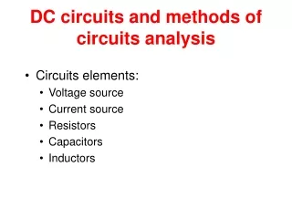
DC Analysis. DC Circuit Analysis. Capacitors and Inductors in DC Circuits have a transient (temporary) response. During the transient period, capacitors build up charge and stop the flow of current (acting like infinite resistors.)


DC Analysis
E N D
Presentation Transcript
DC Analysis Engr. FahmiSamsuri, FKEE, UMP
DC Circuit Analysis • Capacitors and Inductors in DC Circuits have a transient (temporary) response. During the transient period, capacitors build up charge and stop the flow of current (acting like infinite resistors.) • Inductors build up energy in the form of magnetic fields, and become more conductive. In steady-state (long term behavior), capacitors become open circuits and inductors become short circuits.
For DC analysis, you can replace a capacitor with an empty space and an inductor with a wire. The only circuit components that remain are voltage sources, current sources, and resistors. Footer Text
Capacitors and Inductors at DC • DC steady-state (the circuit has been in the same state for a long time), capacitors act like open circuits and inductors act like shorts. The below figures show the process of replacing these circuit devices with their DC equivalents. In this case, all that remains is a voltage source and a lone resistor.
Resistors • If a circuits contains only resistors either in combination of parallel or series connections then an equivalent resistance is determined. Ohm's Law is used to determine the current flowing in the main circuit. A combination of voltage and current divider rules are then used to solve for other required currents and voltages.
Combined parallel and series circuits R1 R2 R3 R4 To calculate V4||V23 To calculate i of R2 & R3
Transient Analysis • A circuit can be analyzed at different points in time. • Whenever a switch is closed in a circuit, the voltages and currents in the circuit take some time to settle down to their final values; the components of voltages and currents that die down are called as transients. • Transientanalysisof a circuit is done at the time of switching to study the effects of the transients as well as to determine the time taken by the system to settle down.
The behavior of the circuit as a function of time is studied under transientanalysis. • The inductors in the circuit are replaced by their equivalent current sources and resistances, and the capacitors in the circuit are replaced by their equivalent voltages sources and resistances. • The circuit voltages and currents are calculated at the time of switching (usually at t = 0); this is the initial condition solution.
The voltages across the capacitors and the currents across the Inductors are used to calculate the circuit voltages and currents at each time step; this is done repeatedly for a designated amount of time and the results are then plotted. • Constraints provide an elegant means of stating relationship among objects that should be maintained by the underlying system.
AC Analysis • The AC analysis is a small signal analysis in the frequency domain. Basically this type of simulation uses the same algorithms as the DC analysis. • The AC analysis is a linear modified nodal analysis. Thus no iterative process is necessary. With the Y-matrix of the components, i.e. now a complex matrix, and the appropriate extensions it is necessary to solve the equation system similar to the (linear) DC analysis.
Non-linear components have to be linearized at the DC bias point. That is, before an AC simulation with non-linear components can be performed, a DC simulation must be completed successfully.
Comparison of Analyses • In dc analysis a voltage or a current or a global parameter (resistor, temperature) is swept - and the resulting voltage resp. current distribution in the network is computed. Important: During this analysis all ac relevant parts (capacitor, inductor) are set to ZERO. This analysis is important for producing characteristic transfer curves like Ic=f(Vbe). DC Analysis
During TRANSIENT analysis first an initial operating point is calculated (based on dc values) and after that all momentary voltages and currents are computed as the result of a time dependent voltage or current source - including, of course, the influence of capacitors and inductors as well as all non-linearities (clipping effects due to voltage limits etc.) Transient Analysis
AC-analysis does NOT take into consideration any non-linearities. Based on the actual bias point the small signal behaviour is analyzed (using the slope of characteristic functions). Therefore, the input signal may be as large as you want (best choice: 1 volt or 1 amp). AC Analysis
Additional Notes • Transient Analysis – SPICE • Lecture notes • AC Analysis - PSPICE