Download
1 / 66
790 likes | 1.58k Vues
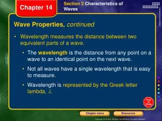
Properties of a stationary wave (2). All particles between two adjacent nodes (within one vibrating loop) are in phase. Video Stationary waves (string) Stationary waves (sound). 4 Interference. When two waves meet, they interfere.

E N D
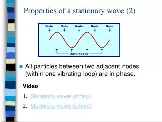
Properties of a stationary wave (2) • All particles between two adjacent nodes (within one vibrating loop) are in phase. • Video • Stationary waves (string) • Stationary waves (sound)
4 Interference • When two waves meet, they interfere. • Superposition occurs to give constructive and destructive interferences. • To produce a permanent interference pattern, the sources must be coherent. • The waves from coherent sources have (1) the same frequency, (2) the same wavelength, (3) constant phase difference.
If their phase difference is not constant, at a certain point, there may be reinforcement at one instant and cancellation at the next. If these variations follow one another rapidly, the interference pattern will change quickly. • The wave causing interference should have roughly the same amplitude. This is to ensure the wave cancel each other to produce a minima (zero amplitude).
S1 resultant P S2 Constructive interference: The waves arrive at a point in phase
Path difference from 2 sources equals , , and so on. S1 resultant P S2 ½l Destructive interference: The waves arrive at a point exactlyout of phase.
Factors affecting the interference pattern • (1) Source separation When source separation increases, the separation between antinodal (or nodal) lines decreases. Increase the separation of two sources
(2) Wavelength When wavelength decreases, the separation between antinodal (or nodal) lines decreases. Decrease the wavelength
Young’s experiment http://www.fed.cuhk.edu.hk/sci_lab/download/project/interference/interference.html
Young’s double-slit experiment • It is very important to use a single light source and a double slit, rather than two light sources. It is because the two sets of light waves passing through the double-slit are coherent. • Since the wavelengths of light waves are very small, the separation between the slits must be very small. • The screen should be placed at an appreciable distance from the slits so that the separation of fringes is observable.
Interference pattern of light • Explanation: • Diffraction of light occurs at each slit. Since the two diffracted waves overlap, interference occurs. • Bright fringes are where constructiveinterference occurs while dark fringes are where destructive interference occurs.
P X a R Q a Y Path difference for Young’s double-slit experiment Since a << D, PX and PY are almost parallel ⇒ q ≈ a and PQY ≈ 90o By geometry q’ = a ⇒q ≈q’ Path difference = PY – PX = QY ≈ a sin q.
P X a R Q a Y Path difference for Young’s double-slit experiment Path difference = a sin q. Constructive interference: If the nth bright fringe is at P, a sin qn = nl ⇒ Destructive interference: If the mth bright fringe is at P, a sin qm = (m – ½)l ⇒
P X a R Q a Y Fringe position Path difference = a sin q. nth bright fringe Let yn be the distance between the nth bright fringe and the central bright fringe. yn = D tan qn≈ D sin qn=
yn = Dy = distance between 2 successive bright fringes = yn – yn-1 = P X a R Q a Y Fringe position
1. The fringes are evenly spaced ( ) 2. The fringe spacing for red light is greater than for blue light. ∴lred > lblue 3. The interference is incomplete because for all fringes except the central bright one, the amplitudes of the two wave-trains are not exactly equal.
Appearance of Young’s interference Fringes http://micro.magnet.fsu.edu/primer/java/doubleslit/index.html • If white light is used the central fringe is white and the fringes on either side are coloured.
Measuring wavelength of light l can be measured by using the formula http://www.matter.org.uk/schools/Content/Interference/doubleslits_1.html
Interference by Thin Films Thin film of soapy water Seashell • Thin film interference patterns seen in A thin layer of oil on the Water of a street puddle
t Parallel-sided Thin Film (1) When a beam of light is incident on to the surface of the film, part of incident light is reflected on the top surface and part of that transmitted is reflected on the lower surface. • Consider a film of soap with uniform thickness in air air If the film is not too thick, the two reflected beams are close together to produce an interference effect. Soap film http://webphysics.davidson.edu/physlet_resources/bu_semester2/c26_thinfilm.html
ray 1 ray 2 air A C phase change of p d film B air Phase change of p • Interference occurs for rays 1 and 2 Suppose the thickness of the film is d and its refractive index is n. Let l be the wavelength of light in air. Consider almost normal incidence (angle of incidence ≈ 0o) Interference due to reflected rays (Optical) Path differencefor rays 1 and 2 = 2nd
ray 1 ray 2 air A C phase change of p d film B air Phase change of p If light travelling in a less dense medium is reflected by a dense medium, the reflected wave is phase-shifted by π. No phase change will be experienced by transmitted rays. (Optical) Path differencefor rays 1 and 2 = 2nd Conditions for constructive interference and destructive interference Bright fringes: 2nd = (m + ½)lwhere m = 0, 1, 2, 3….. (a phase change of p occurs at A) Dark fringes: 2nd = ml where m = 0, 1, 2, 3…..
ray 1 ray 2 air A C phase change of p film d B D air ray 3 ray 4 • Interference due to transmitted rays (ray 3 and ray 4) Bright fringes: 2nd = mlwhere m = 0, 1, 2, 3….. (no phase change of p occurs at B) Dark fringes: 2nd = (m + ½)l where m = 0, 1, 2, 3…..
Blooming of Lenses (1) • The process of coating a film on the lens is called blooming. • A very thin coating on the lens surface can reduce reflections of light considerably. • This makes use of destructive interference of light to reduce the reflection. http://users.erols.com/renau/thinfilm.html
air (n = 1) phase change of p Coating film MgF2 (n = 1.38) Glass (n = 1.72) • Path difference of the rays = 2nd • For destructive interference between rays 1 and 2 2nd = l/2 (both rays undergo a phase change of p) d = l/(4n) Thickness of coating Put l = 5.5 x 10⁻⁷ m, n = 1.38 (refractive index of coating) d = 5.5 x 10⁻⁷ / (4 x 1.38) = 9.97 x 10⁻⁸ m
air (n = 1) phase change of p Coating film MgF2 (n = 1.38) Glass (n = 1.72) Note: • 1 The thickness of the film (coating) should be of ¼ wavelength of light in the film. • 2. With suitable blooming, the reflectance can be reduced from 4% to less than 1%. • 3 The interference is complete for one wavelength only. An average value of l (i.e. green – yellow) is chosen. For red and blue light, the reflection is weakened but not eliminated and bloomed lens appears purple.
no phase change air (n = 1) Coating film MgF2 (n = 1.38) phase change of p Glass (n = 1.72) • While destructive interference occurs between reflected rays, constructive interference occurs between transmitted rays. • If there is constructive interference on one side of the film, there will be destructive interference on the other side (energy conservation).
Brilliant colours of oil film on water Investigating oil film on water Brilliant colours of oil film
Air na = 1.0 qred qblue Constructive interference Constructive interference oil film no= 1.4 water nw = 1.33 • Interference occurs between two wave-trains – one reflected from the surface of the oil and the other from the oil-water interface. • When the path difference gives constructive interference for light of one wavelength, the corresponding colour is seen in the film.
Air na = 1.0 qred qblue Constructive interference Constructive interference oil film no= 1.4 water nw = 1.33 • The path difference varies with the thickness of the film and the angle of viewing, both of which affects the colour produced. • If the film is not thin, for a particular angle of viewing, constructive interference between reflected rays occurs for more than one colour. Therefore, many colours are present in the reflected light. This gives the appearance of white light and no specific colour is seen.
phase change of p Soap film • A soap film mounted on a ring is held vertically. At first the film appears uniformly bright. As the soap drains to the bottom, a series of interference fringes are seen.
phase change of p Soap film • For normal incidence, bright fringes are observed if • 2nd = (m – ½) l , where n is the refractive index of soap, l is the wavelength of light in air, and m = 1, 2, 3, … • Minimum thickness of the film for bright fringe • dmin = l /(4n) • Hence, when the upper part of the film becomes extremely thin < l /(4n), constructive interference does not take place and a black area or black fringe is observed.
1 2 3 4 • As time goes by, the film drains downwards further and does not break, the fringe pattern changes: • Dark area at the top increases and moves downwards. • The number of fringes increases. • Fringes are more closely spaced towards the bottom.
The figure above shows an air wedge formed by a thin film and a glass block. They are separated by a thin piece of paper so that the wedge angle q is very small. • In the arrangement, monochromatic light from a source is partially reflected vertically downwards by a glass plate G. • When a microscope is focused on the wedge, bright and dark equally-spaced fringes are seen. • This is because the reflected rays interfere with each other to form an interference pattern.
Thin Film of Air • Light rays reflected from the upper and lower surfaces of a thin wedge of air interfere to produce bright and dark fringes. • The fringes are equally spaced and parallel to the thin end of the wedge. http://www.gg.caltech.edu/~zhukov/applets/film/applet.html
Phase change of p Thin Film of Air • Consider almost normal incidence. • Path difference of two rays = 2d • For dark fringes, 2d = nλ. • For bright fringes, 2d = (n+½)λ. d θ
d θ = since q is very small. Phase change of p Thin Film of Air, Wedged-shaped (2) Fringe separation For two adjacent dark fringes, Dd = ½[ml – (m – 1)l] = ½l
Note: • 1. If the path difference > coherent length, no fringe is formed. • 2 In order to have a clear fringe pattern, the fringe separation should be increased. This can be done by making the air wedge as thin as possible. • 3 At the practical level, every film absorbs some of the light going through it. Thick films absorb proportionately more than thin ones, thereby reducing the dark and light bands in an interference pattern.
radian = 0.110o d q 5 cm • Applications of air wedge • Measuring diameter of a metal wire Suppose the distance between the 1st fringe and the 91st fringe observed is 16.2 mm and the wavelength of light emitted from the light source is 690 nm. Fringe separation Dx = 16.2 mm / 90 = 0.18 mm Angle of the wedge = If the length of the air wedge is 5 cm, the diameter of the metal wire d ≈ 5 cm x 1.91 x 10-3 = 9.58 x 10⁻³ cm = 9.58 x 10⁻⁵ m
Concave upward Concave downward 2. Testing the flatness of surface • In making of optical ‘flats’, the plate under test is made to form an air wedge with a standard plane glass surface. • Any uneven parts of the surface will show up as irregularities in what should be a parallel, equally-spaced, straight set of fringes.
Find the thickness of the air wedge at P. Wavelength of white light l≈ 5.5 x 10⁻⁷ m x P At P, destructive interference occurs between the reflected rays. Path difference = l 2t = l t = l / 2 = 2.75 x 10⁻⁷ m
What is the thickness of the air wedge at R? x R Find the thickness of the air wedge at Q. Wavelength of white light l≈ 5.5 x 10⁻⁷ m x Q At Q, constructive interference occurs between the reflected rays. Path difference = 1.5 l 2t = 1.5l t = 1.5l / 2 = 4.125 x 10⁻⁷ m
Flatness of Surfaces • Observed fringes for a wedged-shaped air film between two glass plates that are not flat. • Each dark fringe corresponds to a region of equal thickness in the film. • Between two adjacent fringes the change in thickness is λ/2μ. where μ is the refractive index of the film.
Newton’s Rings (AL only) • When a curved glass surface is placed in contact with a flat glass surface, a series of concentric rings is seen when illuminated from above by monochromatic light. These are called Newton’s rings.