Assistive Seating Device for Enhanced Comfort in Sailing
640 likes | 770 Vues
The P12031 project focuses on developing an innovative assistive seating device tailored for sailing, aiming to improve comfort and safety for users. Our team, comprised of experts led by faculty members Edward Hanzlik and Kate Leipold, is gathering critical feedback to ensure our design meets the customer's needs. With features like high corrosion resistance and custom dimensions, our goal is to create a reliable seating option that performs well in challenging marine environments. For live updates, visit our website.

Assistive Seating Device for Enhanced Comfort in Sailing
E N D
Presentation Transcript
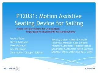
P12031: Motion Assistive Seating Device for Sailing Please view our Website for Live Updates: http://edge.rit.edu/content/P12031/public/Home Project Team: Steven Gajewski Aleef Mahmud Mitchel Rankie Christopher “Chappy” Sullivan Faculty Guide: Edward Hanzlik Technical Mentor: Kate Leipold Primary Customer: Richard Ramos Secondary Customer: Keith Burhans Sponsor: Mark Smith and M.E. Dept. MSD - P12031
Agenda Desired Outcome from Meeting: • Gather critical Feedback on our progress! • Are we headed in the right direction? • Should we change anything before detailed design? • Interactive meeting: question or comment as we go! MSD - P12031 Meeting Date: Wednesday 11/4/2011 Meeting Time: 3:30PM-5:30PM Meeting Location: RIT Engineering #09-4425
Project Description MSD - P12031
Customer Needs MSD - P12031
Engineering Specifications MSD - P12031
Material Selection MSD - P12031 • Ideal material: • High corrosion resistance • High strength properties • Weld-able • Common • AA 6061-T6: • Has all material qualities we are looking for • Very common across all distributors
Recap: Functional Decomposition MSD - P12031
Recap: System Interface MSD - P12031
Detailed Design • Triple Constraint MSD - P12031 Safety
Pedestal Base MSD - P12031 • Pedestal base changes • Re-routed lines (new pulley location) • Taller support tube • Shorter platform
Track Platform MSD - P12031
Material Properties MSD - P12031
Richard Swinging Across MSD - P12031
Richard Swinging Across MSD - P12031
ANSYS Work for Richard Swinging MSD - P12031
Rough Waves MSD - P12031
Rough Waves 1425N-down 25N-Bow MSD - P12031
Rough Waves At Stop At Unsupported At Middle MSD - P12031
Acceleration • The Maximum acceleration the system can handle 4.5 Gs MSD - P12031
Acceleration Bow 5G Stern 4.5G Starboard 4.5G Port 5G Bow 10G Combined Starboard and Sten3.5G Mag = 4.9 MSD - P12031
Passenger Interface MSD - P12031 • The Passenger Interface is a very elaborate subsystem that was further dissected into two sub-subsystems: • Crank System • Seating Support
User Dimensions MSD - P12031 Passenger Interface was heavily driven by the user’s dimensions.
Custom Seat Dimensions MSD - P12031 “ASO seat pan will be 19 wide x 18 long and about 4" tall” - Colleen Wolstenholm, Aspen Seating LLC “Seat pan will have a t-nut fastener heated and sunk into the seat on the inside plastic, then a 1/4-20 stainless knob screwing from the outside of the aluminum tabs to the seat.” - Joe Bieganek,Aspen Seating LLC Aluminum tabs can be welded on to seat plate once we have access to the Custom Seat to align with the bolt location. Waiting for more details on the custom seat.
Benchmarking: Seat MSD - P12031 The Parameters for choosing the seat: • Seat must fit within a common interface with the Custom Seat. • Interface will be aluminum flat plate with the dimensions of 20”wide by 18”long. • Seat Height cannot exceed 30” • Seat must fit within the boundaries of the Sonar Boat. • Seat must have minimal weight. • Seat must be durable in corrosive environment. • Seat must be intended for rigorous activity. • Seat cost must be relatively low compared to the market.
Benchmarking: Seat MSD - P12031 Kirkey 19800 Economy 10 Degree Layback • Versatile mounting. • 17.5”wide by 14.5”long by 35”high with 10⁰recline. • Weighs 13.5lb • Al 5052 has good formability, corrosion resistance and weldability. • Designed for low horse power cars on small tracks. • Stock frame costs $136.60 and the Blue Vinyl cover cost $68.40. Total estimate is about $205. • Catalog: http://kirkeyracing.com/Kirkey_2009_catalog.pdf
Benchmarking: Harness MSD - P12031 The Parameters for choosing the seat: • Harness must fit with the Custom Seat and Commercial Seat. • Harness must restrain user within the confines of the seat. • Harness must be accepted by user for final application. • Harness must be durable in corrosive environment. • Harness cost must be relatively low compared to the market.
Benchmarking: Harness MSD - P12031 enableyourlife.com Wheelchair Butterfly Chest Harness • Harness intended to attach via 4” adjustable straps which can be mounted on the seat. • Harness is designed to restrain disabled users into their wheel chairs while in movement. • User has already voiced his preference for butterfly type harnesses. • Harness material is a versatile nylon webbing and plastic buckle that should not rust. • Harness cost is very low compared to its competitors. • Catalog: http://enableyourlife.com/wheelchair-butterfly-chest-harness.asp
Hand Constraints & Attachment • Used C-5 Grip system as benchmark • System too expensive to purchase • Decided to redesign and fabricate MSD - P12031
Our “C-5” System Hand Tube Pin Hole • Same functionality • Cheaper components • Simple solution Bearing Threaded Insert Casing MSD - P12031
Bearing Specifications Sealed bearing to last in elements Able to withstand larger loads than applied Cheap to replace if needed MSD - P12031
Boat Constraints Needed to know boat dimensions to design everything Shumway provided non dimensioned drawing Took real world measurements to scale drawing MSD - P12031
Boat Constraints Cont. From dimensions we scaled drawing Created the boat itself to make sure system fits inside Created a hybrid 3-D drawing to show walls and important features on boat MSD - P12031
Boat Constraints Cont. MSD - P12031
Seat Tilt and Support • Once boat was laid out design was possible • Decided on permanent tilt for simplicity • Went with 10 degree tilt for comfort and visibility • Seat has built in seat so you are actually tilted 20 -25 degrees • Decided to keep the back of bar in same location • Raised front where pedestal mount is • Therefore system needed to shift forward to prevent contact with sides and traveler • With tilt total height will decrease to miss boom MSD - P12031
Seat Tilt Prelim Design MSD - P12031
Seat Support Design • Once angle and structure was decided we laid out our support system • Single beam for simplicity • Cross beam for support and bearing mount MSD - P12031
Crank Geometry Constraints • Crank center of rotation was to be placed at location relative to seat • Distance between pulleys was fixed by v-belt length • Width of crank fixed by Richard’s dimensions • Seat was a large factor • Seat issues: • Seat drives where crank is • Different seats move crank (different dimensions) • Where seat plate is located • Tilt created difficult geometry MSD - P12031
Crank Center Location • Crank located 23” from back of seat and 12” from seat cushion • Assumed 11” torso and 14” from torso • Used 23” so there is play and space for different seats MSD - P12031
Crank Layout Design • Used Callahan’s system for layout • Shaft set up allows for line drum to rotate as well as steering system to rotate out of the way • Support arm provides strength and constrains rotation of system MSD - P12031
Crank Layout Cont. • Centered line drum over pedestal • Secured support arm with ball lock pin for easy installation MSD - P12031
Points of Adjustability • To change crank location the following dimensions must be changed MSD - P12031
Adjustability Cont. • Grip system will have longer or shorter hand tubes for different should widths • Seat can be moved relative to the plate • Harness size can be changed MSD - P12031
Calculation: Mechanical Advantage MSD - P12031 Mechanical Advantage: • User input force will be amplified through the pulleys and crank sizes. • Current system amplifies to approximately 85lb output. • Current system will amplifies to approximately 150lb output. • Approximately 75% increase
Calculation: Seat Plate MSD - P12031 Seat Plate: • Aluminum 6061-T6 • 20”wide by 18”long by .25”thick • Analyzed through use of ANSYS Classic. • Assume Fixed Support at weld and cross beam. • Case #1: Assume distributed Pressure P across entire plate to represent Richard’s weight of 170lb in normal position. • Case #2: Assume distributed Pressure P across half the plate to represent Richard’s weight of 170lb suddenly thrown to one side while in quick rotation.
Calculation: Seat Plate MSD - P12031 Final conclusion is that the seat will be able to withstand the loading under its current specifications in ideal conditions. No further redesign is recommended at this time.
Calculation: Crank System MSD - P12031 Crank System: • Aluminum 6061-T6 • Analyzed through use of ANSYS Workbench. • Assume Fixed Support at connection points. • Case #1: Normal 20lb applied by user on the crank axis. • Case #2: Extreme case of 170lb applied by user on the crank axis to represent his entire weight being pulled against the crank system. • Case #3: Extreme case of 170lb applied by user on the crank axis to represent his entire weight being pushed onto the crank system.
Calculation: Crank System MSD - P12031 Final conclusion is that the Crank System will be able to withstand the loading under its current specifications. Despite being loaded in the most aggressive scenarios to simulate the entire weight of the user being slammed against and pulled away from the crank, the crank system will still be able to withstand the load.
Calculation: Original Tiller Strut MSD - P12031 Original Tiller Strut : • Aluminum 6061-T6 • Analyzed through use of ANSYS Workbench. • Assume Fixed Support at connection points. • Case #1: Previous load of 85lb on previous design. • Case #2: Enhanced load of 150lb on previous design.
Calculation: Crank System MSD - P12031 Final conclusion is that the Tiller Strut will not be able to withstand the Enhanced load of 150lb generated through mechanical advantage of the new proposed design. Steps must be taken to redesign the Tiller Strut as well to withstand the new load generated in the new design.
Calculation: Tiller Strut Redesign MSD - P12031 Tiller Strut Redesign : • Aluminum 6061-T6 • Beefed up with Aluminum tubes. • Analyzed through use of ANSYS Workbench. • Assume Fixed Support at connection points. • Case #1: Simulates the boat going straight under peak load. • Case #2: Simulates the boat turning left under peak load. • Case #3: Simulates the boat turning Right under peak load.