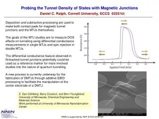
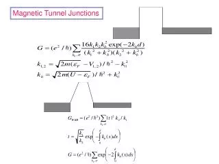
Magnetic Tunnel Junctions
Magnetic Tunnel Junctions. Transfer Hamiltonian. Tunneling Magnetoresistance. Tunneling: see Phil. Mag. 83 , 1255 (2003). k || resolved (partial) DOS in units of states/atom. eV of bcc(100) Fe plotted in the first 2DBZ. Left column is for the majority spin channel

Magnetic Tunnel Junctions
E N D
Presentation Transcript
k|| resolved (partial) DOS in units of states/atom. eV of bcc(100) Fe plotted in the first 2DBZ. Left column is for the majority spin channel and right column is for the minority spin channel. From top to bottom, DOS for a bulk Fe layer, a free surface Fe layer and the isolated electrode surface Fe layer. k|| resolved (partial) DOS in units of states/atom. eV of bcc(100) Fe plotted in the first 2DBZ. Left column is for the majority spin channel and right column is for the minority spin channel. From top to bottom, DOS for a bulk Fe layer, a free surface Fe layer and the isolated electrode surface Fe layer.
k|| resolved (partial) DOS in units of states/atom. eV of fcc(100) Co plotted in the first 2DBZ. Left column is for the majority spin channel and right column is for the minority spin channel. From top to bottom, DOS for a bulk Co layer, a free surface Co layer and the isolated electrode surface Co layer.
Also see for resonant states: O.Wunnicke et al. PRB 65, 064425 (2002).
k|| resolved (partial) tunneling conductance of bcc (100) Fe/vacuum(10)/Fe tunnel junction at an energy 0.05eV below the Fermi level (a) only for the barrier region, and (b) for the entire junction.
k|| resolved (partial) tunneling conductance of the barrier region of a Co junction in the first 2DBZ when the magnetizations of the two electrodes are aligned in parallel(a) majority spin channel, (b) minority spin channel, and (c) antiparallelly aligned. The vacuum barrier is 6 atomic layers thick.
The need to diagonalize basis when more than one state transforms under same irreducible representation C. Uiberacker and P.M. Levy, PRB 64, 193404 (2001);erratum PRB 65, 169904 (2002).
Bias dependence of TMR-trapezoidal barrier JMR ratio vs. bias for free electron trapezoidal barrier model tunnel junction with a Fermi sea depth of 16eV for majority and 3eV for minority spins; square barrier height at zero bias is 1eV measured from Fermi level
Ab-initio calculation of JMR for Co/Vac(6)/Cu(p)Co junction; K. Wang private communication.
Tunneling with semiconducting electrodes For metallic electrodes it is sufficient to have 2-3ML of the magnetic electrode for spin dependent tunneling (SDT) ; therefore it is not the spin polarization of the current that produces SDT. What happens for semiconducting electrodes? As there is little screening of electrons in semiconductors I surmise that the SDT with 2-3ML of magnetic semiconducting electrodes is very different from 20-30 ML. Also, there will be hole as well as electron conduction; particularly for holes spin-orbit coupling plays an important role. The spin-orbit coupling can be detrimental to the polarization of spin currents.
One can conceptualize spin dependent tunneling in two steps: • Presenting spin polarized electrons at the interface of between • the electrode and barrier. This is accounted for by the DOS. • The decay of wavefunction inside the barrier. There are • evanescent states inside the barrier whose decay is given by • an imaginary k vector.
So what’s new? The spin Hall effect: Hirsch (1999), Zhang (2000)* In general the Hall effect is the current or voltage transverse to the applied electric field. This usually appears when one applies a magnetic field perpendicular to the electric field; however in systems that contain spin-orbit coupling one can have preferential scattering of spins to the left or right of the current, so that one can produce a Hall voltage in the absence of a magnetic field. This principle was first enunciated by Mott and has the formed the basis of Mott spin scattering detectors. *
Then we were told there’s an intrinsic SHE It seems not! But can one detect the ISHE?