Download
1 / 49
520 likes | 1.11k Vues
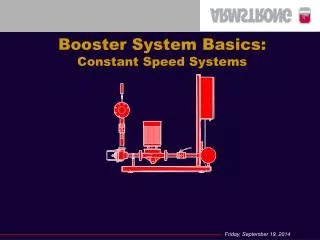
Booster System Basics: Constant Speed Systems. Pressure Booster Systems. WHAT IS A BOOSTER SYSTEM? BOOSTER SIZING REQUIREMENTS BOOSTER SYSTEM CONTROL ENERGY SAVING STRATEGIES DRAWDOWN TANKS. What is a Pressure Booster System?. Pumps.

E N D
Pressure Booster Systems • WHAT IS A BOOSTER SYSTEM? • BOOSTER SIZING REQUIREMENTS • BOOSTER SYSTEM CONTROL • ENERGY SAVING STRATEGIES • DRAWDOWN TANKS
What is a Pressure Booster System? Pumps • All components mounted on a common base, tested and calibrated to site conditions Control Panel Pressure Reducing Valves Headers, Piping and Isolation Valves, Pressure gauges, Solenoid Valve, Aquastat and copper tubing
What you need to size a booster system? • Calculate the total flow requirement for the building • Number of Domestic Water Fixtures • Type of fixtures in the building • Type of building (residential, public, heavy use) • Special services
100 100 HUNTERS CURVE GPM 50 50 50 50 100 100 Fixture Units Total Flow = Total Fixture Units
What you need to size a booster system? • Calculate the total flow requirement for the building • Calculate the total pressure required for the building
Pstat Static Pressure • Based on the vertical boost required above the packaged system manifold • This component never varies
Pfix Fixture Pressure • Required pressure to operate fixture at farthest point from system. • Must overcome valve “start-up” pressure (i.e. 25 PSI min. required for flush valves to operate) • Never varies, this is always required as a minimum
Ploss Packaged System Losses • Systems are designed to have no more than 5psi loss from suction manifold to discharge manifold • This must always be added into pressure calculations
Pcity Available Suction Pressure • Typically varies by about 10-30 PSI • Can vary over time due to growth • Can also vary due to municipal re-structuring
Pfric Friction Losses • Usually calculated at 10% of total static requirement • Typically a very small boost pressure component • Can be larger as in the case of boost over a “campus-style” area or large low-rise building
System Pressure E Fixture pressure D PRV Losses Pump Boost Pressure Static head C B Friction Head A Supply pressure after water meter Pressure Requirement
Pressure Requirement Pump Boost Pressure (TDH) = Fixture Pressure + Package Losses + Static Head + Friction Head - Supply Pressure
Pressure Requirement Boost Pressure = System Pressure - Supply Pressure
Significance of System Flow in Booster Systems • Flow impacts system demand, not pressure - as demand increases, flow must increase at a constant output pressure • Flow governs pump actuation - therefore, flow should govern pump sequencing and actuation • System capacity matched to system flow requirement is most efficient and cost effective for domestic water pressure boosting
What are the most popular methods of booster pump control ? • Flow meter or flow switch • Instrument is in contact with corrosive water therefore requiring more maintenance
What are the most popular methods of booster pump control ? • Flow meter or flow switch • Pressure Switch • Requires non-overloading (NOL) motors • Requires a pressure drop across operating range • Can be unstable in operation resulting in “starving” the system of water (end of curve operation) • Mechanical switches increase possibility of failure
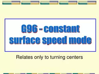
PRESSURE (PSI) 50 Discharge Pressure 40 HP 30 20 Suction Pressure 10 0 50 100 150 200 250 300 350 GPM Effect of Suction Pressure
PRESSURE (PSI) 50 Discharge Pressure 40 HP 30 Suction Pressure 20 Suction Pressure 10 0 50 100 150 200 250 300 350 GPM Effect of Suction Pressure
What are the most popular methods of booster pump control ? • Flow meter or flow switch • Pressure Switch • Current or kW Sensing
Current Sensing • As the flow increases, so does the pump load • The motor must match the pump load • Current / Power draw for motors is proportional to the load (pump flow work)
PRESSURE (PSI) 50 40 PUMP CURVE HP 30 20 Motor Amps 10 0 50 100 150 200 250 300 350 GPM Current - Flow Relationship
PRESSURE (PSI) 50 Discharge Pressure 40 HP 30 20 Motor Amps Suction Pressure 10 0 50 100 150 200 250 300 350 GPM Effect of Suction Pressure
PRESSURE (PSI) 50 Discharge Pressure 40 HP 30 Suction Pressure 20 Suction Pressure 10 Motor Amps 0 50 100 150 200 250 300 350 GPM Effect of Suction Pressure
% Voltage Change - 10 + 10 +11 % Change Full Load Amps - 7 Effects of Voltage Fluctuations on Motors
Current Sensing • Motors sized to match the power requirement • Current sensing allows flexible pump sizing to match the system load profile and energy requirement • Duplex: • Triplex: 33% - 67% capacity split 20% - 40% - 40% capacity split
Current Sensing • Duplex allows up to three steps of sequencing
Current Sensing • Triplex allows up to five steps of sequencing
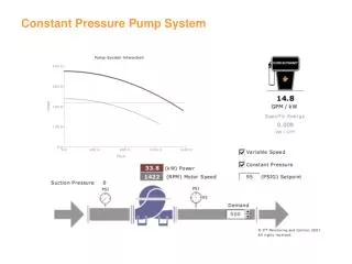
500 450 400 350 Flow Rate ( GPM) 300 250 50-50 Split 200 Actual 150 Consumption 100 50 0 23h00 22h00 21h00 20h00 19h00 18h00 17h00 16h00 15h00 14h00 13h00 12h00 11h00 9h00 10h00 8h00 7h00 6h00 5h00 4h00 3h00 2h00 Time 1h00 0h00 Typical Daily Demand Curve
500 450 400 350 Flow Rate ( GPM) 300 250 50-50Split 200 Actual 150 Consumption 100 50 0 23h00 22h00 21h00 20h00 19h00 18h00 17h00 16h00 15h00 14h00 13h00 12h00 11h00 9h00 10h00 8h00 7h00 6h00 5h00 4h00 3h00 2h00 Time 1h00 0h00 Duplex Booster - 50/50 SplitConventional Split
500 33-67 Split 450 400 350 Flow Rate ( GPM) 300 250 200 50-50 Split Actual 150 Consumption 100 50 0 23h00 22h00 21h00 20h00 19h00 18h00 17h00 16h00 15h00 14h00 13h00 12h00 11h00 9h00 10h00 8h00 7h00 6h00 5h00 4h00 3h00 2h00 Time 1h00 0h00 Duplex Booster - 33/67 Split3 Step Control with No-flow shutdown
Energy Consumption HP = GPM X Feet (Head) 3960 X (Pump Eff) x (Motor Eff) • Smaller pump at lower flows will be more efficient and consume less energy • Smaller motor is more efficient at lower loads
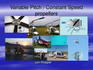
33-67% Energy Savings: 19% 14 12 10 Consumption (kWhrs) 8 6 Actual Consumption 4 50-50 Split 2 33-67 Split 0 23h00 22h00 21h00 20h00 19h00 18h00 17h00 16h00 15h00 14h00 13h00 12h00 11h00 10h00 9h00 8h00 7h00 6h00 5h00 4h00 3h00 2h00 Time 1h00 0h00 Energy SavingsConventional vs. 33/67 Split
Energy SavingsConventional vs. 33/67 Split Total Energy Savings= 19% Energy Cost = $0.12 / kWhr Savings per Year: $2,280
What are the most popular methods of booster pump control ? • Flow meter or flow switch • Pressure Switch • Current or kW Sensing • VFD with pressure transducers
No-Flow Shutdown and Tank Sizing When do you use it? Where should you install it? What size should it be?
Sizing and Selecting Drawdown Tank • Tanks are to be used in systems that do not have a continuous water demand • Tanks should NOT be sized according to booster size • Tanks should be sized to store 20 - 30 Gallons of water (2 - 3 GPM leak loads) • Tanks maintain pressure in piping system and supply small demands to allow pumps to be shutdown
Sizing and Selecting Drawdown Tank • Tank Storage Volume is governed by the Ideal Gas Law • Solving for storage volume gives: • Vstorage = Pdifferential xVTotal Tank(PTotal +PAtmosphere) • 3 factors must be considered
Tank Volume • Vstorage =Pdifferential xVTotal Tank(PTotal +PAtmosphere) • The bigger the tank, the better the storage
Differential Pressure • Tank storage Volume is proportional to the difference in the cut out and cut in pressures of the pumps • The larger the pressure differential the more water that will be stored in the tank • Vstorage =Pdifferential xVTotal Tank(PTotal +PAtmosphere)
Pressure Differential Calculation • Pdifferential = Pstop - Pstart • Pstop = Pressure at the tank when the system shuts down • For adjacent or package mounted tanks, this means the suction pressure plus the shutoff head of the pump • For remote mounted tanks, this is simply the normal system pressure at the location of the tank
Pressure Differential Calculation • Pdifferential = Pstop - Pstart • Pstart = Pressure at the tank when the system starts again down • For adjacent or package mounted tanks, this means the setting on the no flow (call on) pressure switch • For remote mounted tanks, this is simply the system pressure at the location of the tank when the call on pressure switch brings the system back on
Total Pressure • A lower Total Pressure will yield larger water storage for the same pressure differential • Lower Total Pressure allows for lower tank pressure rating • Vstorage =PdifferentialxVTotal Tank(Ptotal +PAtmosphere) • Lower tank pressure rating
Sizing and Selecting Drawdown Tank • All three of these factors must be considered in selecting the appropriate tank • Vstorage = Pdifferential xVTotal Tank(PTotal +PAtmosphere)
Where Should the Tank be Installed ? • Packaged Mounted • Tank water storage may be limited by tank size • Will require higher tank pressure rating • More Costly • Difficult to maneuver due to weight and may require building structural reinforcement.
Where Should the Tank be Installed ? • Adjacent Mounted • Tank is supplied as a loose component for connection on site • Tank is not mounted on skid with pumps • Contractor has freedom to locate tank in mechanical room • System is easier to maneuver
Where Should the Tank be Installed? • Remote Mounted • Roof mounting - Lowers Tank Total Pressure and Tank Pressure Rating Required • Allows for the use of smaller tanks for desired water storage • Contractor has flexibility locating and installing tank
Questions & Answers