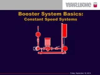
Booster Pump Systems 101 The Basics
Booster Pump Systems 101 The Basics. JON VICKERY VC SYSTEMS & CONTROLS, INC. 8811 Vneture Cove Tampa, Florida 33637 1-800-881-3123 www.vcsystems.net. DESIGN BASICS: Part 1: Terminology Part 2: Understanding what a booster is, when it is needed, and building requirements.

Booster Pump Systems 101 The Basics
E N D
Presentation Transcript
Booster Pump Systems 101The Basics JON VICKERY VC SYSTEMS & CONTROLS, INC. 8811 Vneture Cove Tampa, Florida 33637 1-800-881-3123 www.vcsystems.net
DESIGN BASICS: • Part 1: Terminology • Part 2: Understanding what a booster is, when it is needed, and building requirements. • Part 3: Application, building type, and calculating the load. • Part 3: Sizing and selection of the booster • Part 4: Pump types, selection, and curves. • Part 5: Putting the system together...
GPM – Gallons Per Minutes • PSI – Pressure • TDH – Total Dynamic Head • Suction Pressure – Pressure supplied by the city to the building. • Boost – Pressure output by the booster to achieve system pressure • Water Meter – Component that calculates water use by a building • Backflow Preventer – Component at the street that restricts water in the building from flowing back in to the municipal supply. • Friction Loss – Pressure drop as it travels through pipe, valves, or other components like a water meter or back flow preventer. • Demand / Load – The water consumed by the building, usually calculated in GPM • Flush Valve – Standard reservoir toilet, requires 5 PSI. • Flush Tank – Toilet that has a pressurized tank which is used to flush, requires minimum 25 PSI, recommend 30 PSI. Part 1.1 - Terminology
NPSH(R) – Net Positive Suction Head Required (More in Part 4) • BHP – Break Horsepower (More in Part 4) • Max Rated Horsepower – Max horsepower at run out (More in Part 4) • Duty Point – The required point on a curve where GPM & TDH meet • Shut Off Head – The highest point on the curve when flow is zero • Max Working Pressure – The maximum pressure that can be achieved at shut off plus maximum suction pressure • BAS – Building Automation System • Variable Speed Drive – Electronic component that varies the speed of the motor • Variable Speed Booster System – Booster system that varies motor speed based on demand and changing suction pressure. • Constant Pressure Booster System – Commonly mistaken for constant speed, all booster systems are constant pressure no matter what the control type, as they all maintaining a CONSTANT PRESSURE. Part 1.2 - Terminology
Pressure / TDH • Pressure * 2.31 = TDH • TDH / 2.31 = PSI • Example: 43 PSI * 2.31 = 100’ TDH • Example: 150’ TDH / 2.31 = 65 PSI • Horsepower / BHP @ Duty Point • ((GPM * TDH) / 3960) * Pump Efficiency (At Duty Point, typically 65-70%) • Example: • 100 (GPM) * 100’ (TDH) = 10,000 • 10,000 / 3960 = 2.525 • 2.525 / 68% = 3.71 BHP = 5 HP Required • Max Working Pressure • Shut off head + max suction pressure • Example: • 300’ TDH @ Shut Off = 130 PSI • 130 PSI + 60 PSI Max Suction = 190 PSI Max Working Pressure Part 1.3 – Terminology (Formulas)
City Supply – Most Common, this is a positive suction pressure (given in PSI) supplied by the municipality. Ranges anywhere from 20 PSI to 100 PSI and typically known by the engineer. This information is gathered from a flow test given by the cities Fire Department. The flow test will give static pressure, and residual pressure and will typically flow 900-1100 GPM during the test. • Static Pressure – This is the average and/or maximum suction pressure. • Residual Pressure – Residual is the minimum suction pressure. • Other suction sources exist and will be covered in Booster Training 201. This will include break tanks, cisterns, and other applications. Part 2.1 – Water Source(SYSTEM SUPPLY)
Suction Source & Suction Pressure – To properly start to size the building, you must know the minimum suction pressure. (Rule of thumb – if unknown, 30 PSI is a common figure.) • Building Static Height – This is total height of the building. The engineer should be able to tell you this or he should be able to tell you his starting elevation and highest elevation. This difference of the two elevations is the height. (Rule of thumb – This can also be determined by number of floors if the structure for low & mid rise buildings. The number of floors multiplied by 12 feet per floor. For example: A 10 Story building will be close to 120’ in total height.) • Delivery Pressure – This is the pressure desired at the top floor/fixture. This is typically 35 to 40 PSI however the engineer will give you this. Part 2.2 – Building Conditions (Part 1)
Part 2.2 – Building Conditions (Part 2) • Losses - Backflow Preventer or RPZ, Meter, Friction Loss (Pipe Run), Water Softening System, internal booster losses... Below are typical figures, specific applications may differ… • Backflow Preventer – 8 PSI • Meter – 4 PSI • Friction Loss – 4 PSI • Internal Booster Losses – 5 PSI • Water Softener – 20 PSI • THESE ARE THE GENERAL PIECES TO THE PUZZLE • Sample sizing in the following slides will be for a 150 unit / 10 story hotel.
PART 3.1 - PRESSURE • CITY PRESSURE • MINIMUM – 40 PSI • MAXIMUM - 50 PSI • DEVICES INSTALLED • METER – 8PSI • BFP – 4PSI • Friction – 2 PSI • DIFFERENTIAL ELEVATION • 10 STORIES • FLAT GRADE – 110’ • ELEVATION @ TOP – 225’ • OTHER LOSSES • BOOSTER – 5 PSI • DELIVERY PRESSURE – 35 PSI STEP 1: 40 PSI – 14 PSI = 26 PSI MINIMUM @ THE BOOSTER STEP 2a: 225’ Elevation – 110’ Elevation = 115’ Static Height or 50 PSI STEP 2b: 10 Stories * 12’ Per Floor = 120’ Static Height or 52 PSI STEP 3: 50 PSI (Static Height) + 35 PSI (Delivery) = 85 PSI (SYSTEM PRESSURE) STEP 4: 85 PSI (System) – 26 PSI (Min Suc) = 59 PSI + 5 PSI (Booster Loss) = 64 PSI BOOST Required
BASIC NET BOOST CALCULATION THIS SIZING TOOL IS AVAILABLE ON THE WEBSITE
PART 3.2 - DEMAND • Demand is calculated by all of the fixtures that will consume water. • Bathrooms (Toilets & Sinks) • Kitchens (Sink & Dishwasher) • Laundry • Pool Fill • Cooling Tower Fill • Hose Bibs • Etc… • The engineer will typically give you the total fixture count or a preselected GPM if he has already done his own calculation. • Building type has a great impact on GPM and selections, this will be covered in Booster Training 202. ** For this exercise we will be using 300 GPM as the system capacity for a 150 unit Hotel.
CALC BY FIXTURE UNIT THIS SIZING TOOL IS AVAILABLE ON THE WEBSITE
SYSTEM GPM AND PUMP SPLIT THIS SIZING TOOL IS AVAILABLE ON THE WEBSITE
PART 4.1 - HOW MANY PUMPS DO I NEED? HORSEPOWER REDUNDANCY LOAD PROFILE OWNER DATA POWER SUPPLY FOOTPRINT BUDGET • Sample Conditions: • 300 GPM @ 64 PSI Boost CUSTOM OR “STANDARD” SYSTEM
LIFE CYCLE VS FIRST CAPITAL COSTS ENERGY COST VS FIRST CAPITAL COSTS COMPLEXITY OF CONTROLS (OWNER ABILITY) SPACIAL CONCERNS FOR INSTALLATION SERVICEABILITY OF THE EQUIPMENT TYPE & CONSTRUCTION OF THE PUMPS 3RD PARTY CERTIFICATION, UL OR ETL LISTED NEED FOR REDUNDANT SUPPLY LOAD PROFILE VS TYPE OF SYSTEM LOAD PROFILE VS NUMBER OF PUMPS PART 4.2 - SYSTEM DESIGN CONSIDERATIONS
There are many pump types available and just as many optional configurations of those types. However TWO pump types dominate 95% of the booster market. Part 4.3 – Pump Types 2. Vertical Multistage (VMS) – Higher cost, higher efficiency, ideal for mid to high rise applications, or where all stainless steel construction is required. 1. End Suction (ES) – Cost effective and more commonly used for low to mid rise applications. See VC Series for VC Systems brand of end suction pumps designed specifically for our packages.
Pump Efficiency Motor Speed Impeller Trim Horsepower Lines PART 4.4a – Pump Curve (Components)
Motor Speed – The motor speed for pumps in a booster system are typically 3500 RPM. Some cases require a 1750 RPM selection which uses a completely different curve. • Horsepower Lines – Each line represents the horsepower of the motor required by the particular selection. The duty point does NOT determine the HP. That is the number one mistake most representatives make! • Run Out – Run out is the furthest point on the curve for the selected trim. PART 4.4b – Pump Curve (Definitions)
Sample Conditions: • 300 GPM • 64 PSI Boost • (147’ TDH) • Sample Conditions: 33% Each Pump • Triplex System - 100 GPM @ 147’ TDH Part 4.5a – Pump Selection (End Suction) • The correct selection is 7.5 HP.
Sample Conditions: • 300 GPM • 64 PSI Boost • (147’ TDH) • Sample Conditions: 50% Each Pump • Duplex System - 150 GPM @ 147’ TDH Part 4.5b – Pump Selection (End Suction) • The correct selection is 10 HP.
Sample Conditions: • 300 GPM • 64 PSI Boost • (147’ TDH) • Sample Conditions: 33% Each Pump • Duplex System - 150 GPM @ 147’ TDH • The proper selection still requires 10 HP with VMS style pumps with the CR32-3-2. However the system cost would increase by 15-30%. Part 4.5c – Pump Selection (VMS)
LIFE CYCLE VS FIRST CAPITAL COSTS ENERGY COST VS FIRST CAPITAL COSTS COMPLEXITY OF CONTROLS (OWNER ABILITY) SPACIAL CONCERNS FOR INSTALLATION SERVICEABILITY OF THE EQUIPMENT TYPE & CONSTRUCTION OF THE PUMPS 3RD PARTY CERTIFICATION, UL OR ETL LISTED NEED FOR REDUNDANT SUPPLY LOAD PROFILE VS TYPE OF SYSTEM LOAD PROFILE VS NUMBER OF PUMPS PART 6.1 – Putting the system together.
WHEN SHOULD WE USE VARIABLE SPEED? ABSOLUTELYALWAYS “WITH A FEW EXCEPTIONS”
ENERGY SAVINGS: NORMALLY 30 TO 50% CAN BE EXPECTED. IMPROVED PROCESS CONTROL: STABLE SYSTEM PRESSURE IMPROVED SYSTEM RELIABILITY: REDUCED PUMP WEAR REDUCED MAINTENANCE: IMPROVED TIME BETWEEN SERVICE PM REDUCED WATER HAMMER: SOFT START, REDUCED SURGE & INRUSH CONTROL VALVES: PRV’S REQUIRE PERIODIC MAINTENANCE SYSTEM CONTROL: VFD’S HAVE BETTER CONTROL AT LOW FLOW BENEFITS OF USING VFD’S SOME EASY TO QUANTIFY, OTHERS NOT SO EASY
Sample Conditions: • 300 GPM • 40 PSI Boost • (70’ TDH) • 85 PSI System • Sample Conditions: 50% Each Pump • Duplex System - 150 GPM @ 70’ TDH • Add • VFDs • 50 PSI Suction • The 10 HP Selection from earlier is running at around 5 BHP at maximum demand when suction pressure is at its peak. The speed reduction of almost 30-40% leaders to thousands in electricity saved. Part 4.5 – Pump Selection & VFD