Download
1 / 25
320 likes | 688 Vues
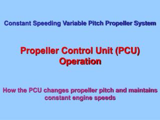
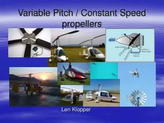
The Constant Speed Propeller. Introduction. Describe how power is controlled with a Constant Speed Propeller Describe how the speed of the propeller is set and controlled State the limitations on the engine and propeller Describe the 2 elements of a Constant Speed Propeller Unit

E N D
Introduction • Describe how power is controlled with a Constant Speed Propeller • Describe how the speed of the propeller is set and controlled • State the limitations on the engine and propeller • Describe the 2 elements of a Constant Speed Propeller Unit • Describe the failure modes of the Constant Speed Propeller
Objectives • State how to control power and engine RPM with a constant speed propeller • State the limitations of RPM and engine power • List the 2 main elements of a Constant Speed Propeller system • Explain how the Pitch Change Mechanism and the Speed Governor work • State the failure modes of the Constant Speed Propeller
Limitations • The Slingsby Firefly T67M-Mk2 • The MAP must not exceed hundreds of RPM +4 • i.e. If the RPM is 2300, the max allowed MAP is 27” • The RPM must not exceed 2700.
Two Main Elements • Speed Governor • Senses speed of the engine • Provides pressurised oil, hydraulic lock or a path to sump for oil to the pitch change mechanism • Pitch Change Mechanism • Changes pitch of the blades depending on the oil pressure from the Speed Governor
Failure ModeUnderspeed • Underspeed • Caused by excessive pitch • Loss of oil Pressure • Failure of speed governor • Failure of Pitch Change Mechanism • Actions • Check oil pressure • Check MAP above 15” If not open throttle • Exercise RPM through whole range • Refer to checklist
Failure ModeOverspeed • Overspeed • Caused by excessively fine pitch • Speed Governor failure • Pitch Change Mechanism failure • Actions • Use throttle to keep RPM within limits • Leave RPM control at mid range • Reduce speed 80kts • Refer to failure checklist
Summary • How power is controlled with a Constant Speed Propeller • How the speed of the propeller is set and controlled • Limitations on the engine and propeller • The 2 elements of a Constant Speed Propeller Unit • The failure modes of the Constant Speed Propeller
Questions • State how to control power and engine RPM with a constant speed propeller • State the limitations of RPM and engine power • List the 2 main elements of a Constant Speed Propeller system • Explain how the Pitch Change Mechanism and the Speed Governor work • State the failure modes of the Constant Speed Propeller