GEOMETRIC OPTICS
GEOMETRIC OPTICS. By DR.AMER ISMAIL ABUIMARA JORADNIAN BOARD OF OPHTHALMOLOGY INTERNATIONAL COUNCIL OF OPHTHALMOLOGY PALESTINIAN BOARD OF OPHTHALMOLOGY. Is the study of light and images using geometric principles .

GEOMETRIC OPTICS
E N D
Presentation Transcript
By DR.AMER ISMAIL ABUIMARA JORADNIAN BOARD OF OPHTHALMOLOGY INTERNATIONAL COUNCIL OF OPHTHALMOLOGY PALESTINIAN BOARD OF OPHTHALMOLOGY
Is the study of light and images using geometric principles . • Geometric optics uses linear rays to represents the paths traveled by light .
PINHOLE IMAGING • Make a pinhole near the center of a large sheet of aluminum foil, light a candle , and extinguish all other illumination in the room . hold a sheet of plain white or , better ,waxed paper about 2 ft from the candle , and place the pinhole midway between the paper and the candle . observe an inverted image of the candle flame on the paper • Moving the pinhole closer to the candle while keeping the paper stationary yields a larger image.
An object may be regarded as a collection of points . • Geometric optics treats every point of an object as a point source of light . • An object has an infinite number of point sources , and each source point is infinitesimally small. • Light radiates in all directions from each point on an object .
Stars behave as point sources . the point source is mainly a conceptual tool : it is usually easier to understand an optical system by concentrating on the light radiating from a single object point or a few points .
For every object point , there is a specific image point . in optics the term ( conjugate ) refers to these corresponding object and image points . • A ray is a geometric construct indicating the path of light as it travels from an object point to the corresponding image point . rays represent only a path .they do not indicate The amount ( intensity ) or wavelength of light traveling along the path .
Usually light travels from left to right . • Pencil of light is a small collection ( bundle ) of light rays traveling in the same direction .pinhole images are usually too faint to be useful . • A solar eclipse can be safely observed with a pinhole. • Several pinholes yield several images . • The pinhole restricts the brightness not the size of the image .
Clinical examples for conjugate points are : • retinoscopy • direct ophthalmoscopy .
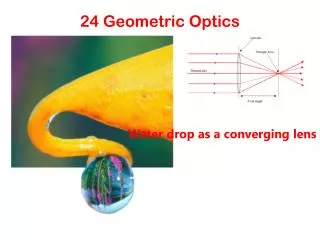
IMAGING WITH LENSES AND MIRRORS • Repeat the pinhole imaging demonstration , but replace the pinhole with a +6 D sphere trial lens , and note the improvement in the image . vary the distances among the candle ,lens and paper , and observe the variety of different image characteristics that can be obtained • Deferent lenses provide an even broader range of images .
Compared with the pinhole , the lens allows much more light from each object point to traverse the lens and ultimately contribute to the image . • Generally lenses produce better images than do pinholes .
What are the disadvantages of lenses ??? • image only in one location . • mirrors produce images in much the same way as lenses .
Most optical systems are rotationally symmetric about their long axis . this axis of symmetry is the optical axis . although the human eye is not truly rotationally symmetric , it is nearly symmetric .
OBJECT CHARACTERISTICS • By location with respect to the imaging system • By luminosity ( if they produce their own light . • If not they only can be imaged if they are reflective and illuminated .
IMAGE CHARACTERISTICS • magnification • location • quality • brightness
MAGNIFICATION • Three types are considered in geometrical optics : • transverse • angular • axial • the ratio of the height of an image to the height of the corresponding object is known as transverse magnification .
transverse magnification = image height / object height • object and image heights are measured perpendicular to the optical axis and , by convention , are considered positive when the object or image extends above the optical axis and negative , below the axis .
for example : if the object height is + 6cm , and the image height is -3cm , thus the transverse magnification is – 0.5 , meaning that the image is inverted and half as large as the object . • transverse magnification applies to linear dimensions . for example , a 4cmx 6cm object imaged with a magnification of 2 produces an 8cmx 12cm image . both width and length double , yielding a fourfold increase in image area .
generally , the multiplication sign ,X, is used to indicate magnification . • most optical systems have a pair of nodal points. • Occasionally the nodal points overlap , appearing as a single point , but technically they remain a pair of overlapping nodal points .
The nodal points are always on the optical axis and have an important property . • From any object point , a unique ray passes through the anterior nodal point . this ray emerges from the optical system along the line connecting the posterior nodal point to the conjugate image point .
These rays form 2 angles with the optical axis . • The essential property of the nodal points is that these 2 angles are equal for any selected object point . because of this feature , nodal points are useful for establishing a relationship among transverse magnification , object distance, and image distance .
Regardless of the location of an object , the object and the image subtend equal angles with respect to their nodal points. • Transverse magnification= image height = image distance object height object distance
As practical matter , object and image distances must obey a sign convention consistent with the established convention for transverse magnification . • Object distance is measured from the object to the anterior nodal point , and image distance is measured from the posterior nodal point to the image . • For a simple thin lens immersed in a uniform medium such as air , the nodal points overlap in the center of the lens .
ANGULAR MAGNIFICATION • Is the ratio of the angular height subtended by an object seen by the eye through a magnifying lens , to the angular height subtended by the same object viewed without the magnifying lens . • By convention , the standard viewing distance for this comparison is 25cm . • For small angles , the angular magnification provided by a simple magnifier (P) is independent of the actual object size : • M= (1/4)P or M= P/4
AXIAL MAGNIFICATION • Also known as longitudinal magnification , is measured along the optical axis . • For small distances around the image plane, axial magnification is the square of the transverse magnification . • Axial magnification = ( transverse magnification )2
IMAGE LOCATION • Refractive errors result when images formed by the eye’s optical system are in front of or behind the retina . • Image location is specified as the distance ( measured along the optical axis ) between a reference point associated with the optical system and the image .
The reference point depends on the situation . it is often convenient to use the back surface of a lens as reference point . the back lens surface is usually at the same location as the posterior nodal point , but it is easier to locate . • Frequently , image distance is measured from the posterior principal point to the image .
The principal points like the nodal points , are a pair of useful reference points on the optical axis . the nodal points and principal points often overlap . • Whatever reference point is used to measure image distance , the sign convention is always the same . • When the image is to the right of the reference point , image distance is positive ; when the image is to the left of the reference point , the distance is negative .
DEPTH OF FOCUS • Perform the basic imaging demonstration with a lens as described before ( imaging with lenses and mirrors ) , and notice that if the paper is moved forward or backward within a range of a few millimeters , the image remains relatively focused . with the paper positioned outside this region , the image appears blurred .
The size of this region represents the depth of focus , which may be small or large depending on several factors . • In the past , depth of focus was of concern only in the management of presbyopia . however , it is an important concept in refractive surgery as well .
Depth of focus applies to the image . depth of field is the same idea applied to objects . • If a camera or other optical system is focused on an object , nearby objects are also in focus . • Objects within the range of depth of field will be in focus , whereas objects outside the depth of field will be out of focus .
IMAGE QUALITY • Careful examination reveals that some details in an object are not reproduced in the image . • Images are imperfect facsimiles , not exact scaled duplicates of the original object . • Consider an object 50 cm in front of a pinhole 1mm in diameter . paper is placed 50 cm behind the pinhole , so the magnification is -1 . • A small pencil of rays from each object point traverses the pinhole aperture .
Each object point produces a 2-mm diameter spot in the image . these spots are called blur circles . this term is somewhat misleading because off-axis object points technically produce elliptical spots in the image . • In addition, this analysis ignores diffraction effects that make the spot larger and more irregular .
Regardless , each object point is represented by a blur circle in the image , and the farther the image is from a pinhole , the larger the blur circle in the image . • To the extent that these blur circles overlap , the image detail is reduced ( blurred ). • To some extent , the loss of detail is mitigated with the use of a smaller pinhole .
A smaller pinhole gives a dimmer , but more detailed , image . however the smaller the pinhole , the more that diffraction reduces image quality . • While a smaller blur circle preserves more detail, the only way to avoid any loss of detail is to produce a perfect point image of each object point . • Theoretically , if a perfect point image could be produced for every point of an object , the image would be an exact duplicate of the object .
A perfect point image of an object point is called a ( stigmatic image ) . • “ stigmatic “ is derived from the Greek word stigma , which refers to a sharply pointed stylus . • Loss of detail occurs in lens and mirror imaging as well , because light from an object point is distributed over a region of the image rather than being confined to a perfect image point .
Generally , lenses focus light from a single object point to a spot 10-100micrometer across . • This is better than a typical pinhole , but the shape of the spot is very irregular . • The term ( blur circle ) is especially misleading when applied to lenses and mirrors . • A better term is ( point spread function ) , which describes the way light from a single object point is spread out in the image .
To summarize , a stigmatic image is a perfect point image of an object point . • However , in most cases , images are not stigmatic . instead , light from a single object point is distributed over a small region of the image known as a blur circle or , more generally , a point spread function PSF . • The image formed by an optical system is the spatial summation of the PSF for every object point .
The amount of detail in an image is related to the size of the blur circle or PSF for each object point . • The smaller the PSF , the better the resemblance between object and image .
LIGHT PROPAGATION • OPTICAL MEDIA AND REFRACTIVE INDEX • Light travels through a variety of materials , such as air , glass , plastics , liquids , crystals , some biological tissues , the vacuum of space , and even some metals .
A medium is any material that transmits light . • Light travels at different speeds at different media . light moves fastest in a vacuum and slower through any material . • The refractive index of an optical medium is the ratio of the speed of light in a vacuum to the speed of light in the medium and is usually denoted in mathematical equation by the lowercase letter n .
The speed of light in a vacuum is 299,792,458m/s. this is approximately 300,000 km/s or 186.000 miles / s . • In 1983 the Systeme International defined a meter as the distance light travels in a vacuum during 1/299,792,458 of a second . • Refractive index is always greater than or equal to 1 .
In computations , it is often easier to work with the refractive index of a material than directly with the speed of light . • n = speed of light in vacuum speed of light in medium
refractive index is quite sensitive to a material’s chemical composition . • a small amount of salt or sugar dissolved in water changes its refractive index . • because refractive index is easy to measure accurately , chemists use it to identify compounds or determine their purity . • glass manufacturers alter the refractive index of glass by adding small amount of rare earth elements . • until recently , clinical labs screened for diabetes by measuring the refractive index of urine .