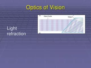
LIGHT: Geometric Optics
LIGHT: Geometric Optics. The Ray Model of Light. Light travels in straight lines under a wide variety of circumstances Light travels in straight line paths called RAYS. Optical Instruments: Refractive. CONVERGING LENS. Causes parallel rays to converge Produces real and virtual images.

LIGHT: Geometric Optics
E N D
Presentation Transcript
The Ray Model of Light • Light travels in straight lines under a wide variety of circumstances • Light travels in straight line paths called RAYS
CONVERGING LENS • Causes parallel rays to converge • Produces real and virtual images. • Focal Length is positive.
Ray Tracing for Converging Lens Ray 1: Parallel emerge through F Ray 2: Through F emerge Parallel Ray 3: Straight through center
The Lens Equation • 1/do + 1/di = 1/f • m = hi/ho = - di/do • m is magnification • ho/hi = do/di
DIVERGING LENS • Causes parallel rays to diverge • Produces only small-virtual images. • Focal Length is negative.
Ray Tracing for Diverging Lens • Focal length is negative for any diverging instrument. • Image distance is negative for virtual images. • Virtual image produced will be smaller than object.
Compound Microscope The eyepiece is placed such that the image formed by the objective falls at first focal point of the eyepiece. The light thus emerges as parallel rays.
Total Internal Reflection • Red light is incident on the glass-air boundary at an angle greater than the critical angle. • although red, when compared to blue and yellow, has the lower index of refraction.
Can you explain this? • The pattern formed is from a converging lens.
Chromatic Aberration • Each color has a different focal point. • The refractive index is different for each wavelength.
Reflection • Law of Reflection • The angle of incidence equals the angle of reflection • The incident and reflected rays lie in the same plane with the normal to the surface
Diffuse vs Specular Reflection • Diffuse Reflection • Light incident upon a rough surface • Law of reflection still holds; Normals not ll. • Specular Reflection • Mirror like reflection • All Normals are parallel
Image formation by a Plane Mirror • Image distance equals the object distance. • Image size equals the object size. • Virtual image formed.
CONVEX MIRROR • Produces only small-virtual images. • Focal Length and Radius are negative. • Anti-Theft, Rear-View, Safety
CONCAVE MIRROR Real image formed by Converging Rays Virtual image formed by Diverging Rays • Produces both Real and Virtual Images • Real images can be magnified or reduced • Virtual images are always magnified.
CONCAVE MIRROR • Real Virtual • Real images can be magnified or reduced • Virtual images are always magnified.
f = r/2 f is focal length r is radius ho/hi = do/di h is height d is distance o is object i is image 1/do + 1/di = 1/f m = hi/ho = - di/do m is magnification Equations to Apply