Download
1 / 51
620 likes | 2.01k Vues
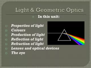
Geometric Optics. The Ray Model of Light. Although light is actually an electromagnetic wave , it generally travels in straight lines. We can describe many properties of light by assuming that it travels in straight-line paths in the form of rays. .

E N D
Geometric Optics The Ray Model of Light Although light is actually an electromagnetic wave, it generally travels in straight lines. We can describe many properties of light by assuming that it travels in straight-line paths in the form of rays. A ray is a straight line along which light is propagated. In other contexts, the definition of ray might be extended to include bent or curved lines. A light ray is an infinitely thin beam of light. Of course, there really isn’t such a thing, but the concept helps us visualize properties of light.
In this lecture, I am going to “cover” two lecture’s worth of material by skipping most of the mathematics.* “Cover” means “go so fast that the students don’t get it, but the teacher’s conscience is satisfied.” That’s OK. Geometric optics is descriptive modeling, with mathematics. It is not the “right” way to deal with light. So I’m going too fast, skipping the math (which is the part you came to see), and presenting models. Lec20s, under “supplementary material,” has the math. *51 slides, 50 minutes, 1 slide per minute, twice as fast as the experts say you can go and have your audience keep up
Light rays from some external source strike an object and reflect off it in all directions. We only see those light rays that reflect in the direction of our eyes. If you can see something, it must be reflecting light! Zillions of rays are simultaneously reflected in all directions from any point of an object. We won’t try do draw them all! Just enough representative ones to understand what the light is doing.
Index of Refraction Light travels in a straight line except when it is reflected or when it moves from one medium to another. Refraction—the bending of light when it moves from one medium to a different one—takes place because light travels with different speeds in different media. The speed of light in a vacuum is c = 3x10⁸ m/s. The index of refraction of a material is defined by where c is the speed of light in a vacuum and v is the speed of light in the material.
Because light never travels faster than c, n 1. For example, for water, n = 1.33 and for glass, n 1.5. Example: Calculate the speed of light in diamond (n = 2.42).
Refraction: Snell’s Law When light moves from one medium into another, some is reflected at the boundary, and some is transmitted. The transmitted light is refracted (bent). This figure shows refraction. The angle 1 is called the angle of incidence, and the angle 2 is called the angle of refraction.
Light passing from air (n 1) into water (n 1.33). Light bends towards the normal to the surface because it slows down in water. http://www.phy.ntnu.edu.tw/java/light/flashLight.html Light passing from water (n 1.33) into air (n 1). Light bends away from the normal to the surface because it speeds up in air.
air (n1) air (n1) 1 1 2 2 water (n2) water (n2) Snell’s law, also called the law of refraction, gives the relationship between angles and indices of refraction: is the angle the ray makes with the normal!
x 1 H D 2 Coin-in-the-bowl demo (if time). Example:Calculate the apparent depth of a coin one meter below the surface of water. (Angles have been exaggerated for ease of viewing). n1 Light reflected off the coin actually follows the solid yellow path. Your brain “thinks” light travels in a straight line path, and imagines the light followed the dotted line path. The coin appears to be a distance H beneath the surface of the water. n2
x 1 H D 2 You’ll have to look at lec20s.ppt if you want to see all the beautiful math that went here (there were a couple of interesting steps). n2
Total Internal Reflection; Fiber Optics Recall Snell’s law: Suppose n2>n1. The largest possible value of sin(2) is 1 (when 2 = 90). The largest possible value of sin(1) is This value of is called the critical angle, C. For any angle of incidence larger than C, all of the light incident at an interface is reflected, and none is transmitted.
1 < C 1 close to C 1 1 > C Visualization here.
http://hyperphysics.phy-astr.gsu.edu/hbase/phyopt/totint.htmlhttp://hyperphysics.phy-astr.gsu.edu/hbase/phyopt/totint.html Total internal reflection explains the disappearing coin trick (which I’ll show if there is time).
The picture below is for a prism, but it also explains why no light reaches your eyes from a coin under a glass of water.
application: fiber optics http://laser.physics.sunysb.edu/~wise/wise187/janfeb2001/reports/andrea/report.html
application: swimming underwater If you are looking up from underwater, if your angle of sight (relative to the normal to the surface) is too large, you see an underwater reflection instead of what’s above the water.
application: perfect mirrors (used in binoculars) application: diamonds
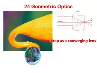
Thin Lenses; Ray Tracing A convex surface has its middle part bent towards you as you look at it. A double convex lens has two convex surfaces, and is called a “converging lens.” Sorry about the colors. I changed the background color, but don’t want to take the time to change all the diagram colors.
A concave surface has its middle part bent away from you as you look at it. A double concave lens has two concave surfaces, and is called a “diverging lens.” The axis of one of these lenses is a straight line through its center, perpendicular to both surfaces.
Light rays striking a convex lens are bent towards the axis at both surfaces. If the lens is infinitesimally thin, all light rays striking the lens parallel to the axis converge at the same point. The point at which the rays converge is called the “focal point.”
For a lens with spherical surfaces, the rays do not quite converge at the focal point, but if the lens is very thin and the object very far away compared to the diameter of the lens, then the rays very nearly converge. We will consider thin lenses in this section. The focal point of a thin convex lens is the point where the image of an infinitely distant object is formed. http://webphysics.ph.msstate.edu/javamirror/ipmj/java/clens/
The focal length, f, is the distance along the lens axis of the focal point from the center of the lens. A an incoming ray parallel to the axis will cross the axis at the focal point F. F f Light rays not parallel to the axis will all converge on the focal plane. F' F f A converging lens like the one shown has focal points on both sides of the lens. focal plane The two focal lengths may differ (if the two surfaces have different shapes). The light rays from an object to the left actually converge at F, not at F'.
We will be studying the images formed by thin lenses. To study the image qualitatively, we use ray tracing to form the image. Only two rays are needed to determine the location of the image from a point on the object. For redundancy, we use three rays. An incident ray parallel to the lens axis passes through F. F A ray through the center of the lens. F' A ray through F' which emerges from the lens parallel to the axis. http://www.physics.brocku.ca/faculty/sternin/120/applets/Lenses/ Image points for other points on the object are found similarly; this lets us complete the image of the object.
We follow the same procedure to find the image for a diverging lens. F' F The image “appears” to be on the same side of the lens as the object; that’s why F and F' have been switched compared to the double convex lens!
The Lens Equation The lens equation describes the position and size of an imaged formed by a lens. The derivation is simple geometry, and can be done for both converging and diverging lenses.
The result is where f is the focal length of the lens, do is the distance from the object to the lens, and di is the distance from the lens to the object. This equation uses these sign conventions: F is + for converging lenses and – for diverging lenses dO is + if object is on side of lens that light comes from (and – otherwise) di is + if image is on opposite side of lens to light source (and - otherwise) image height hi is + if image is upright and – if image is inverted (object height hO is always +)
The magnification of a lens is the image height divided by the object height, and from the figures used to derive the lens equation,
Problem Solving for Lenses Brief litany for solving lens equations: draw a picture draw a ray diagram define and label focal lengths, distances, and heights OSE solve algebraically, then numerically
Images formed by convex lenses may be real… …or they may be virtual.
Example:What are the position and size of the image of a 7.6 cm high flower placed 1 m from a +50 mm focal length converging lens? Example: What is the position and size of the image of an object placed 10 cm away from a +15 cm focal length converging lens? Example:Where must a small insect be placed if a 25 cm focal length diverging lens is to form a virtual image 20 cm in front of the lens? Good links: http://www.physics.brocku.ca/faculty/sternin/120/applets/Lenses/ http://www.cs.unc.edu/~dorianm/academics/comp235/lenstrace/javaapplet/index.htmlhttp://webphysics.ph.msstate.edu/jc/library/22-6/ http://webphysics.ph.msstate.edu/javamirror/ipmj/java/clens/
I R Reflection: Image Formation by a Plane Mirror Light striking a surface may be reflected, transmitted, or absorbed. Reflected light leaves the surface at the same angle it was incident on the surface: The angles are measured relative to the surface normal.
Reflection from a smooth surface is specular (mirror like). Reflection from a rough surface is diffuse (not mirror like). http://acept.la.asu.edu/PiN/rdg/reflection/reflection.shtml http://www.mic-d.com/java/specular/
do di Flat (Plane) Mirrors Plane mirrors form virtual images; no light actually comes from the image. The solid red rays show the actual light path after reflection; the dashed red rays show the perceived light path. ho hi The object distance and image distance are equal: dO=di. The object height and image height are equal: hO=hi. The magnification of a plane mirror is therefore one.
Formation of Images by Spherical Mirrors We will begin by experimenting with several different spherical mirrors. Like lenses, spherical mirrors can be concave or convex. http://physics.bu.edu/py106/notes/Reflection.html
Parallel rays striking a convex spherical mirror do not focus precisely at a single point. However, if the mirror is small compared to its radius of curvature, then the rays essentially all focus at a single point. Just as we assumed thin lenses, we will assume mirrors with large radii of curvature. In “real life” you would minimize the aberration by using a parabolic mirror.
Let’s get definitions and terminology out of the way first. I am borrowing the good illustrations I found at http://www.citycollegiate.com/chapter14_Xa.htm. Spherical mirrors are made from polished sections cut from a spherical surface. The center of curvature, C, is the center of the sphere, of which the mirror is a section. Of course, you don’t really make these mirrors by cutting out part of a sphere of glass.
The radius of curvature is the radius of the sphere, or the distance from P to C. The Principal Axis is the line that passes through the center of curvature and the center of the mirror (P in the previous drawing).
A beam of light parallel to the principal axis will pass through the focal point, F, after being reflected off the mirror surface. The focal length, f, is the distance from P to F. Then f = r / 2, where r is the radius of curvature of the mirror. Light rays from an object at infinity will pass through the focal point, F. (In this picture, the radius of curvature is called R.)
As we did for thin lenses, we can determine image position and orientation by tracing three rays. A ray drawn parallel to the principal axis passes through the focal point. A ray “passing through” F reflects parallel to the axis. F A ray perpendicular to the mirror reflects back through the center of curvature. image from http://hyperphysics.phy-astr.gsu.edu/hbase/geoopt/mirray.html#c3
For a concave mirror, object inside F, the image is upright, virtual, and larger than the object. To construct the image for an object further away from the mirror than F, we trace the “same” three rays…
A ray drawn parallel to the principal axis passes through the focal point. A ray “passing through” F reflects parallel to the axis. A ray perpendicular to the mirror reflects back through the center of curvature. The image is inverted, real (because light rays actually pass through the image position), and smaller than the object.
http://www.glenbrook.k12.il.us/gbssci/phys/mmedia/optics/rdcmb.htmlhttp://www.glenbrook.k12.il.us/gbssci/phys/mmedia/optics/rdcmb.html http://www.glenbrook.k12.il.us/gbssci/phys/mmedia/optics/rdcmc.html
Before we consider the convex mirror, let’s look at the equation relating object and image positions and sizes. From geometry: Hey! The mirror equation is the same as the lens equation! Yup. But the sign conventions are different. dO, dI, or f on reflecting side are + hI is – if image is inverted
Example:A 1.5 cm high diamond ring is placed 20 cm from a concave mirror whose radius of curvature is 30 cm. Determine the position and size of its image.
We’ve looked at the images in concave mirrors. Now let’s look at convex mirrors. A ray drawn parallel to the principal axis “passes through” the focal point. We can skip ray 2 (see slides 11 and 13). A ray perpendicular to the mirror reflects back through the center of curvature. The author of this figure (at hyperphysics) used a different “third” ray.
The image is virtual, upright, and smaller than the object, no matter where you place the object. The mirror equations on slide 15 are still valid.
Example:A convex rearview car mirror has a radius of curvature of 40 cm. Determine the location of the image and its magnification for an object 10 m from the mirror. beautiful math goes here