
Mass Rate Balance
E N D
Presentation Transcript
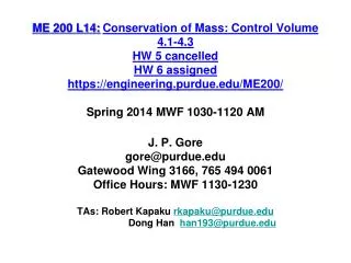
ME 200 L14:Conservation of Mass: Control Volume 4.1-4.3 HW 5 cancelled HW 6 assigned https://engineering.purdue.edu/ME200/Spring 2014 MWF 1030-1120 AMJ. P. Gore gore@purdue.eduGatewood Wing 3166, 765 494 0061Office Hours: MWF 1130-1230TAs: Robert Kapaku rkapaku@purdue.edu Dong Han han193@purdue.edu
time rate of change of mass contained within the control volume attime t time rate of flow of mass in across inlet i attime t time rate of flow of mass out across exit e attime t (Eq. 4.1) Mass Rate Balance
(Eq. 4.2) Mass Rate Balance In practice there may be several locations on the boundary through which mass enters or exits. Multiple inlets and exits are accounted for by introducing summations: Eq.4.2 is the mass rate balance for control volumes with several inlets and exits.
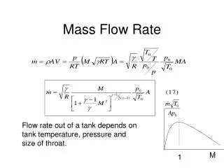
(Eq. 4.4b) where V is velocity v is specific volume Mass Flow Rate(One-Dimensional Flow) • Flow is normal to the boundary at locations where mass enters or exits the control volume. • All intensive properties are uniform with position over each inlet or exit area (A) through which matter flows.
How long does a 50 gallon drum take to fill if H2O is added at 2 gallons/minute and density remains constant? If a 2 inch hose is currently feeding the water, find the average velocity of water in the hose. If the time to fill needs to be reduced to 25%, and only one hose can be used, what size hose would be needed? Control Volume Basic Equations Solution 1 Water 2 Example
(Eq. 4.6) (mass rate in) (mass rate out) Mass Rate Balance(Steady-State Form) • Steady-state: all properties are unchanging in time. • For steady-state control volume, dmcv/dt = 0.
R 134a enters the condenser of a refrigeration system operating at steady state and 9 bar, 50 ºC, through a 2.5 cm diameter pipe. At the exit, the pressure is 9 bar, the temperature is 30 ºC, and the velocity is 2.5 m/s. The mass flow rate of the entering refrigerant is 6 kg/min. Determine: the velocity at the inlet, in m/s, and the diameter of the exit pipe, in cm. Find V1 = ? in m/s d2 = ? in cm System Basic Equations Solution 1 • P1 = 9 bar • T1 = 50 ºC • d1 = 2.5 cm • m1 = 6 kg/min • P2 = 9 bar • T2 = 30 ºC • V2 = 2.5 m/s R-134a 2 Example 6 kg/min = π/4(0.025 m)2 V/0.0247 m3/kg V1 = 5.03 m/s d2 = 2.07 cm
A direct contact feed-water heater is shown in the sketch. Water at 7 bars and 40 C enters through a 25 cm2 port and is heated by steam entering at 7 bars and temperature of 200 C at a flow rate of 40 kg/s. The resulting saturated liquid leaves the FWH at 7 bars. Find: Mass flow rate at inlet 2 and exit 3. Assumptions: Steady state Solution 2 • P2 = 7 bars • T2= 40 ºC • A2 = 25 cm2 • P3 = 7 bars • Sat. Liquid • A3V3=0.06m3/s FWH 3 Example: Feed Water Heater 1 • P1 = 7 bars • T1= 200 ºC • m1 = 40 kg/s Basic Equations
A direct contact feed-water heater is shown in the sketch. Water at 7 bars and 40 C enters through a 25 cm2 port and is heated by steam entering at 7 bars and temperature of 200 C at a flow rate of 40 kg/s. The resulting saturated liquid leaves the FWH at 7 bars. Find: Mass flow rate at inlet 2 and exit 3. Assumptions: Steady state Solution 2 FWH 3 • P3 = 7 bars • Sat. Liquid • A3V3=0.06m3/s • P2 = 7 bars • T2= 40 ºC • A2 = 25 cm2 Example: Feed Water Heater 1 • P1 = 7 bars • T1= 200 ºC • m1 = 40 kg/s State 2 is defined. Find v2 and then design the volume flow rate and the area of the pipe.
Example: Aircraft Jet Engine Video http://www.youtube.com/watch?v=ON0sVe1yeOk ME 200