Download
1 / 56
560 likes | 575 Vues
This paper discusses the concept of beta-beams, a novel approach to creating neutrino beams through the beta decay of radioactive ions. The authors outline the beta-beam concept, progress in the field, challenges, and propose a European Neutrino Oscillation Facility. The study explores different ion choices, including Helium-6 for antineutrinos and Neon-18 for neutrinos. Overall, the aim is to produce high-energy, pure beams of electron neutrinos through the use of existing infrastructure.

E N D
Beta-beams:A neutrino factory based on radioactive ions M. Benedikt, A. Fabich and M. Lindroos, CERN on behalf of the Beta-beam Study Group http://cern.ch/beta-beam BENE06/CARE06 Beta-beam team
Acknowledgements • All colleagues in EURISOL • My CERN colleagues working on beta-beams: • Michael Benedikt, Adrian Fabich, Steven Hancock, Elena Wildner • Prof. Carlo Rubbia • Yacine Kadi, Vasilis Vlachoudis, Alfredo Ferrari • Mauro Mezzetto and Pierro Zuchelli • Andreas Jansson at FNAL • All other colleagues who helped with and supported this work • My colleagues at ANL • My wife and children Beta-beam team
Outline • Beta-beam concept • EURISOL DS scenario • Layout • Progress of work • Challenges • Beyond the EURISOL baseline • High gamma Beta-beams • Electron capture Beta-beams • High-Q vlaue Beta-beams • FNAL Beta-beam • European Design Study proposal for a European Neutrino Oscillation Facility • Summary Beta-beam team
Neutrinos • A mass less particle predicted by Pauli to explain the shape of the beta spectrum • Exists in at least three flavors (e, m, t) • Could have a small mass which could significantly contribute to the mass of the universe • The mass could be made up of a combination of mass states • If so, the neutrino could “oscillate” between different flavors as it travel along in space Beta-beam team
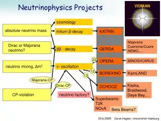
n3 Dm223= 3 10-3eV2 n2 n1 Dm212= 3 10-5 - 1.5 10-4 eV2 OR? n2 n1 Dm212= 3 10-5 - 1.5 10-4 eV2 Dm223= 3 10-3eV2 n3 q23(atmospheric) = 450 , q12(solar) = 300 , q13(Chooz) < 130 Unknown or poorly known even after approved program: 13 , phase , sign of Dm13 Neutrino oscillationsCKM in quark sector -> MNS in neutrino sector • Three neutrino mass states (1,2,3) and three neutrino flavors (e,m,t) 2 Beta-beam team A. Blondel
Ions move almost at the speed of light Introduction to beta-beams • Beta-beam proposal by Piero Zucchelli • A novel concept for a neutrino factory: the beta-beam, Phys. Let. B, 532 (2002) 166-172. • AIM: production of a pure beam of electron neutrinos (or antineutrinos) through the beta decay of radioactive ions circulating in a high-energy (~100) storage ring. • First study in 2002 • Make maximum use of the existing infrastructure. Beta-beam team
Aim: production of (anti-)neutrino beams from the beta decay of radio-active ions circulating in a storage ring Similar concept to the neutrino factory, but parent particle is a beta-active isotope instead of a muon. Beta-decay at rest n-spectrum well known from electron spectrum Reaction energy Q typically of a few MeV Accelerated parent ion to relativistic gmax Boosted neutrino energy spectrum: En2gQ Forward focusing of neutrinos: 1/g Beta-beam n n 6He boost g=100 Beta-beam Basics Beta-beam team
EURISOL scenario The EURISOL scenario • Based on CERN boundaries • Ion choice: 6He and 18Ne • Relativistic gamma=100/100 • SPS allows maximum of 150 (6He) or 250 (18Ne) • Gamma choice optimized for physics reach • Based on existing technology and machines • Ion production through ISOL technique • Bunching and first acceleration: ECR, linac • Rapid cycling synchrotron • Use of existing machines: PS and SPS • Achieve an annual neutrino rate of either • 2.9*1018 anti-neutrinos from 6He • Or 1.1 1018 neutrinos from 18Ne • Once we have thoroughly studied the EURISOL scenario, we can “easily” extrapolate to other cases. EURISOL study could serve as a reference. Beta-beam team
The EURISOL beta-beam Beta-beam team
Guideline to n-beam scenarios based on radio-active ions • Low-energy beta-beam: relativisticg < 20 • Physics case: neutrino scattering • Medium energy beta-beam: g ~ 100 • EURISOL DS • Today the only detailed study of a beta-beam accelerator complex • High energy beta-beam: g >350 • Take advantage of increased interaction cross-section of neutrinos • Monochromatic neutrino-beam • Take advantage of electron-capture process • High-Q value beta-beam:g ~ 100 Accelerator physicists together with neutrino physicists defined the accelerator case of g=100/100 to be studied first (EURISOL DS). Beta-beam team
Which Radioactive ion is best? • Factors influencing ion choice • Need to produce reasonable amounts of ions. • Noble gases preferred - simple diffusion out of target, gaseous at room temperature. • Not too short half-life to get reasonable intensities. • Not too long half-life as otherwise no decay at high energy. • Avoid potentially dangerous and long-lived decay products. • Best compromise • Helium-6 to produce antineutrinos: • Neon-18to produce neutrinos: Beta-beam team
In-flight and ISOL “ISOL: Such an instrument is essentially a target, ion source and an electromagnetic mass analyzer coupled in series. The apparatus is aid to be on-line when the material analyzed is directly the target of a nuclear bombardment, where reaction products of interest formed during the irradiation are slowed down and stopped in the system. H. Ravn and B.Allardyce, 1989, Treatise on heavy ion science In-Flight: ISOL: Post system Gas catcher Driver-beam Thin target Thick hot ISOL target Beta-beam team
6He production from 9Be(n,a) • Converter technology preferred to direct irradiation (heat transfer and efficient cooling allows higher power compared to insulating BeO). • 6He production rate is ~2x10¹³ ions/s (dc) for ~200 kW on target. Converter technology: (J. Nolen, NPA 701 (2002) 312c) Beta-beam team
Producing 18Ne and 6He at 100 MeV • Work within EURISOL task 2 to investigate production rate with “medical cyclotron” • Louvain-La-Neuve, M. Loislet Beta-beam team
Low duty cycle, from dc to very short bunches… • …or how to make meatballs out of sausages! • Radioactive ions are usually produced as a “dc” beam but synchrotrons can only accelerate bunched beams. • For high energies, linacs are long and expensive, synchrotrons are cheaper and more efficient. Beta-beam team
60 GHz « ECR Duoplasmatron » for gaseous RIB 2.0 – 3.0 T pulsed coils or SC coils Very high density magnetized plasma ne ~ 1014 cm-3 Small plasma chamber F ~ 20 mm / L ~ 5 cm Target Arbitrary distance if gas Rapid pulsed valve ? • 1-3 mm 100 KV extraction UHF window or « glass » chamber (?) 20 – 100 µs 20 – 200 mA 1012 per bunch with high efficiency 60-90 GHz / 10-100 KW 10 –200 µs / = 6-3 mm optical axial coupling optical radial (or axial) coupling (if gas only) P.Sortais et al. Beta-beam team
Charge state distribution! Beta-beam team
20 bunches B SPS t 2 ms 2 ms SPS: injection of 20 bunches from PS. Acceleration to decay ring energy and ejection. PS: 1 s flat bottom with 20 injections. Acceleration in ~1 s to ~86.7 Tm.. B B 1 s 1 s PS PS t t RCS: further bunching to ~100 ns Acceleration to ~ 8 Tm. 16 repetitions during 1 s. Post accelerator linac: acceleration to ~100 MeV/u. 20 repetitions during 1 s. 60 GHz ECR: accumulation for 1/20 s ejection of fully stripped ~50 ms pulse. 20 batches during 1 s. t t Target: dc production during 1 s. 1 s 1 s 7 s From dc to very short bunches Beta-beam team
Intensity evolution during acceleration Cycle optimized for neutrino rate towards the detector • 30% of first 6He bunch injected are reaching decay ring • Overall only 50% (6He) and 80% (18Ne) reach decay ring • Normalization • Single bunch intensity to maximum/bunch • Total intensity to total number accumulated in RCS Bunch 20th 15th 10th 5th 1st total Beta-beam team
Dynamic vacuum • Decay losses cause degradation of the vacuum due to desorption from the vacuum chamber • The current study includes the PS, which does not have an optimized lattice for unstable ion transport and has no collimation system • The dynamic vacuum degrades to 3*10-8 Pa in steady state (6He) • An optimized lattice with collimation system would improve the situation by more than an order of magnitude. C. Omet et al., GSI P. Spiller et al., GSI Beta-beam team
Ions move almost at the speed of light What is important for the decay ring? • The atmospheric neutrino background is large at 500 MeV, the detector can only be open for a short moment every second • The decay products move with the ion bunch which results in a bunched neutrino beam • Low duty cycle – short and few bunches in decay ring • Accumulation to make use of as many decaying ions as possible from each acceleration cycle Only “open” when neutrinos arrive Beta-beam team
SPS SPS SPS Injection into Decay ring • Ejection to matched dispersion trajectory • Asymmetric bunch merging Beta-beam team
Injected beam Injected beam after one turn Deviated beam Injection • Injection is located in a dispersive area • The stored beam is pushed near the septum blade with 4 “kickers”. At each injection, a part of the beam is lost in the septum • Fresh beam is injected off momentum on its chromatic orbit. “Kickers” are switched off before injected beam comes back • During the first turn, the injected beam stays on its chromatic orbit and passes near the septum blade • Injection energy depends on the distance between the deviated stored beam and the fresh beam axis envelopes (cm) Septum blade Horizontal envelopes at injection s (m) Optical functions in the injection section Beta-beam team
Injection Beta-beam team
Rotation Beta-beam team
Merging Beta-beam team
Repeated Merging Beta-beam team
energy time Test experiment in CERN PS • Ingredients • h=8 and h=16 systems of PS. • Phase and voltage variations. S. Hancock, M. Benedikt and J-L.Vallet, A proof of principle of asymmetric bunch pair merging, AB-Note-2003-080 MD Beta-beam team
bb Momentum collimation merging LHC project report 773 p-collimation injection decay losses Arc Straight section Arc Straight section Particle turnover • ~1 MJ beam energy/cycle injected equivalent ion number to be removed ~25 W/m average • Momentum collimation: ~5*10126He ions to be collimated per cycle • Decay: ~5*10126Li ions to be removed per cycle per meter Beta-beam team
Decay losses • Losses during acceleration • Full FLUKA simulations in progress for all stages (M. Magistris and M. Silari, Parameters of radiological interest for a beta-beam decay ring, TIS-2003-017-RP-TN). • Preliminary results: • Manageable in low-energy part. • PS heavily activated (1 s flat bottom). • Collimation? New machine? • SPS ok. • Decay ring losses: • Tritium and sodium production in rock is well below national limits. • Reasonable requirements for tunnel wall thickness to enable decommissioning of the tunnel and fixation of tritium and sodium. • Heat load should be ok for superconductor. FLUKA simulated losses in surrounding rock (no public health implications) Beta-beam team
primary collimator Optical functions (m) Deposited Power (W/m) s (m) Collimation and absorption • Merging: • increases longitudinal emittance • Ions pushed outside longitudinal acceptance momentum collimation in straight section • Decay product • Daughter ion occurring continuously along decay ring • To be avoided: • magnet quenching: reduce particle deposition (average 10 W/m) • Uncontrolled activation • Arcs: Lattice optimized for absorber system OR open mid-plane dipoles s (m) Straight section: Ion extraction et each end A. Chance et al., CEA Saclay Beta-beam team
Absorber outside beam-pipe Absorber outside beam-pipe Absorber in beam pipe Model for absorbers Horizontal Plane Beam Pipe Dipole 1 Dipole 2 1 m 1 m 6 m 6 m 2 m 2 m Beta-beam team
Decay ring magnet protection • Absorbers checked (in beam pipe): • No absorber, Carbon, Iron, Tungsten Theis C., et al.: "Interactive three dimensional visualization and creation of geometries for Monte Carlo calculations", Nuclear Instruments and Methods in Physics Research A 562, pp. 827-829 (2006). Beta-beam team
Longitudinal penetration in coil Power deposited in dipole Coil Abs Coil Abs Coil No absorber Stainless Steel Carbon Beta-beam team
Impedance, 340 steps! Below 2.3 GHz, a total of 340 steps (170 absorbers) would add up to 0.5 mH, which seems really high. lowest cut-off (2.3 GHz) Im{Z}/W Impedance of one step (diameter 6 to 10 cm or 10 to 6 cm): L = 1.53 nH f/GHz Beta-beam team
Possible new solution Cu or SS Between dipoles Top view, midplane 60 degrees In dipoles Cu or SS sheets with 60 degrees opening on the sides beams y [m] Beta-beam team
Results for heat deposition Value for LHC Magnet > 4.5 mWatt/cm3 : we have margin, load line more favorable, cooling channels possible to introduce. Next step: Complete heat deposition and shielding calculations with detailed decaying beam (tracking studies) Beta-beam team
Intra Beam scattering, growth times • Results obtained with Mad-8 • 6He • 18Ne Beta-beam team
And what next? • Beyond EURISOL… Beta-beam team
Production • Major challenge for 18Ne • Workshop at LLN for production, ionization and bunching this spring • New production method proposed by C. Rubbia! Beta-beam team
Missed opportunities A new approach for the production Beam cooling with ionisation losses – C. Rubbia, A Ferrari, Y. Kadi and V. Vlachoudis in NIM A 568 (2006) 475–487 “Many other applications in a number of different fields may also take profit of intense beams of radioactive ions.” 7Li(d,p)8Li 6Li(3He,n)8B 7Li 6Li See also: Development of FFAG accelerators and their applications for intense secondary particle production, Y. Mori, NIM A562(2006)591 Beta-beam team
Very advanced gas target in paper by C. Rubbia et al. • The gas jet target may follow the principle of a Supersonic Gas Injector (SGI) implemented for fuelling and diagnostics of high-temperature fusion plasma [12] in several Tokamak, NSTX (USA), Tore Supra (France), HT-& and HL-1M (China), normally operated with H2, D2 and He gases. • The volume of gas (at 250 Torr) is about 4.3m3/s, corresponding to 7:46 1025 atoms=s or 248 g/s. Beta-beam team
Collection using “a catcher” in paper by Carlo Rubbia et al. “The technique of using very thin targets in order to produce secondary neutral beams has been in use for many years. Probably the best known and most successful source of radioactive beams is ISOLDE.” B form compounds and has never been produced in from a solid ISOL target. Can we use “Flourination” and extract BF3? Beta-beam team
Problems with collection device • A large proportion of beam particles (6Li) will be scattered into the collection device. • The scattered primary beam intensity could be up to a factor of 100 larger than the RI intensity for 5-13 degree using a Rutherford scattering approximation for the scattered primary beam particles (M. Loislet, UCL) • The 8B ions are produced in a cone of 13 degree with 20 MeV 6Li ions with an energy of 12 MeV±4 MeV (33% !). Beta-beam team
Why do we gain with such an accumulation ring? • Left: Cycle without accumulation • Right: Cycle with accumulation. Note that we always produce ions in this case! Beta-beam team
Multiple targets and ECR sources with accumulation ring Target • Multiple target and multiple ECR sources • Proton beam split between 7 targets i.e. 1.4 MW of protons in total on all targets • 1 second accumulation time in the ECR source • 0.1 seconds between injections into linac and Accumulation ring • Accumulation of 10 bunches in SPS • ECR pulse: 2 1011 ions per pulse • Annual rate: 1 1018 (without accumulation ring 4 1017) • Drawback: Expensive and complicated! ECR Target ECR Target ECR Target ECR Target ECR Target ECR Target ECR • Multiple target and single ECR sources • Proton beam split between 7 targets i.e. 1.4 MW of protons in total on all targets • 0.1 second accumulation time in the ECR source • 0.1 seconds between injections into linac and Accumulation ring • Accumulation of 10 bunches in SPS • ECR pulse: 1.4 1011 ions per pulse • Annual rate: 1 1018 (without accumulation ring 4 1017) • Drawback: Efficiency in the transport from target to ECR! Target Target Target Target ECR Target Target Beta-beam team Target
EC: A monochromatic neutrino beam Beta-beam team
Long half life – high intensities • At a rate of 1018 neutrinos using the EURISOL beta-beam facility: Beta-beam team
Gamma and decay-ring size, 6He New SPS Civil engineering Magnet R&D Beta-beam team
US studies • Tevatron most realistic scenario • Comparable fast acceleration in all energy regimes • gtop=350 • About 70% survival probability for 6He • Compare with 45% in the EURISOL DS • (2 seconds accumulation time considered) • Reduced decay losses and activation during acceleration • Several studies on the physics reach exist, but annual neutrino rates have to be reviewed. Beta-beam team