Real-Time Clock Communication and Command Management for MSB
This guide focuses on managing Real-Time Clock (RTC) communications and commands for the MSB, particularly with hardware version 2. It covers issuing commands, altering schedules, and querying states efficiently. The document details the structure of packets, including start bytes and command identifiers, and provides instructions on communicating with LEDs and sensors. Additionally, it discusses how to reset systems and save schedules to EEPROM. Key topics include the command parser, sampling rates, and the synchronization process for effective interaction with the MSB.

Real-Time Clock Communication and Command Management for MSB
E N D
Presentation Transcript
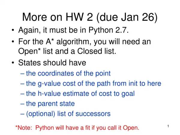
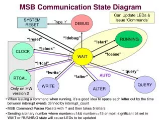
DEBUG CLOCK ALTER QUERY RTCAL WRITE RUNNING WAIT MSB Communication State Diagram Can Update LEDs & Issue ‘Commands’ SYSTEM RESET Type ‘r’ “!debug” “!reset” “!start” Only on HW version 2 “!clock” “!cease” “!rtcal” “!query” “!write” AUTO “!alter” • When issuing a command when running, it’s a good idea to space each letter out by the time between interrupt events defined by interrupt_count • MSB Command Parser Resets with ‘!’ and then takes 5 letters • Sending a binary number where number>=1&& number<=15 or most-significant bit set in WAIT or RUNNING state will cause LEDs to be updated
Receiving a Packet from MSB • MSB will begin ALL packets with 2 start bytes • START_BYTE_1 = '#‘ • START_BYTE_2 = '|' • Start bytes are followed by 1 to 2 bytes to identify the contents of packet • NOTE: Do not send start bytes when sending data to the MSB. The commands used to change states performs the synchronization. If you make a mistake, the character ‘!’ restarts the counter.
Alter Schedule State • After sending “alter” command, send the desired schedule • MSB will verify schedule and will return the schedule that it has calculated based on your requested schedule • The interrupt count is equal to the number of interrupts that will be generated in 10 seconds. • Refer to Spreadsheet for Sensor Calculations • Max Sampling Rate = interrupt count • Min Sampling Rate = 0.1 Hz • Sensors sampling frequency is multiplied by 10 (except microphone) to allow users to obtain the 0.1 Hz sample rate by entering 1. • A sampling rate of 0 disables the sensor struct schedule_msg { uint16_t interrupt_count; // number of interrupts per 10 sec uint16_t mic_hz; // Mic sample rate uint16_t accelometer_hz; // Accelerometer sample rate x 10 uint16_t amb_light_hz; // Amb Light sample rate x 10 uint16_t barometer_hz; // Barometer sample rate x 10 uint16_t compass_hz; // Compass sample rate x 10 uint16_t dals_hz; // DALS sample rate x 10 uint16_t humidity_hz; // Humidity sample rate x 10 uint8_t power; // Power Saving Bits - 3 LSB -Accel/Compass/DALS uint8_t mic_gain; // Microphone gain };
Write State • You may save your current schedule to the EEPROM of the device by issuing the “write” command. • On reset/power on the default schedule is read from the EEPROM.
Query State • Send identifying byte to request packet • Do NOT send a full packet only need a byte to request the response packet • 4 types of requests • Current Schedule (Binary 0x40) • Calibration Information (Binary 0x20) • LEDs State (Binary 0x10) • RTC registers (Binary 0x02) • After responding to request system automatically returns to WAIT state. Calibration Information Packet START_BYTE_1 START_BYTE_2 CALIBRATION_PKT // packet ID uint16_t msb_board_number uint8_t hardware_version uint8_t major_software_version uint16_t minor_software_version uint16_t barometer_calibration_word1 uint16_t barometer_calibration_word2 uint16_t barometer_calibration_word3 uint16_t barometer_calibration_word4 uint8_t mic_gain_value LED Packet START_BYTE_1 START_BYTE_2 LED_PKT // packet ID uint8_t leds_value (see LED encoding) Schedule Packet START_BYTE_1 START_BYTE_2 SCHEDULE_PKT // packet ID schedule_msg (struct)
Version • The calibration packet also contains information about the version. • Hardware Version Values • 0 = Original rectangle board for imote1 • 1 = 1st imote2 board • 2 = 2nd imote2 board w/ SD and Bluetooth (Both Rev A & B) • Major Software Version • Significant changes to the code will receive a new major version number • Minor Software Version • Used to keep track of bug fixes and other minor changes • Hardware Version Verify: • The MSB performs a hardware version verify when booting to verify the hex file loaded is meant for the board • An incorrect hex version is identified by the MSB continually blinking its LEDs during boot.
The Real Time Clock (RTC) • Available on select versions of the 2nd iMote2 board. • Register contents of the RTC (datasheet) are passed between the MSB and host unchanged. • “!clock” command sets all RTC registers except the calibration register. After sending “!clock”, send 7 bytes for registers 0 – 6. • “!rtcal” command sets RTC calibration register. Send calibration register byte after “!rtcal”. • “!query” followed by 0x02 returns all 8 registers in order. All 0xFFs are returned if the RTC cannot be queried.
Bit Encoding 00000001 00101000 NOTE: Only need 1st byte to determine Packet Type, 2nd byte for sensors packet. Packet Type Identifiers RTC_PKT = 0x02; ERROR_PKT = 0x04 MIC_PKT = 0x08; LED_PKT = 0x10; CALIBRATION_PKT = 0x20; SCHEDULE_PKT = 0x40; POWER_PKT = 0x80; SENSOR_PKT = 0x00(… or 0x01, see note) NOTE: Ignore zero bit (byte & 0xfe) Example to Determine Packet Type if(byte1 & 0xfe) { if (byte1 & RTC_PKT) pktType = RTC; else if(byte1 & LED_PKT)) pktType = LED; else if (byte1 & MIC_PKT) pktType = MIC; else if(byte1 &CALIBRATION_PKT) pktType = CALIBRATION; else if(byte1 &SCHEDULE_PKT) pktType = SCHEDULE; else if(byte1 & POWER_PKT) pktType = POWER; } else { pktType = SENSORS; }
Bit Encoding 00000001 00101000 Sensor Identifiers ACCEL = 0x01; DALS_VISIBLE = 0x02; DALS_INFRARED = 0x04; COMPASS = 0x08; BAROMETER = 0x10; BAROMETER_TEMP = 0x20; HUMIDITY = 0x40; HUMIDITY_TEMP = 0x80; AMB_LIGHT = 0x0100; Example Sensor Parser if (sensors & ACCEL) { accel_x_axis = combine(pkt[index++], pkt[index++]); accel_y_axis = combine(pkt[index++], pkt[index++]); accel_z_axis = combine(pkt[index++], pkt[index++]); } else if (sensors & DALS_VISIBLE) { dals_visible_light = pkt[index++]; } else if (sensors & DALS_INFRARED) { dals_infrared_light = pkt[index++]; } else if ( sensors & COMPASS) { compass = combine(pkt[index++], pkt[index++]); ….
Error States • Inserted in the code are error states that should not occur. If the system starts sending error packets and the Blue LED is on please send me: • The character it is sending in the error packet over the serial port • The schedule you were running • Any additional information (e.g. what you were trying to do) • The additional error hex will move to an error state if the MSB drops information. If you do not load the additional error hex the MSB will drop packets silently when the UART transmission queue is full. Getting behind in UART transmission is ONLY likely to occur when using flow control. Error Codes INCORRECT_FIRMWARE = 'F' TIME_SLICE_OVERRUN = 'I' MIC_MEMORY_OVERRUN = 'B' // these errors added with the extra debug OVERFLOW_SENSOR_READINGS_BUFFER = 'S' OVERFLOW_MIC_READINGS_BUFFER = 'M' Error Packet START_BYTE_1 START_BYTE_2 ERROR_PKT // packet ID uint8_t error_code
Data Packets uint16_t sensors; uint8_t time_counter; uint16_t interrupt_counter; uint16_t accel_x_axis; uint16_t accel_y_axis; uint16_t accel_z_axis; uint8_t amb_light_resistance; uint16_t amb_light; uint16_t bar_temperature; uint16_t barometer; uint16_t compass; uint8_t dals_visible_light; uint8_t dals_infrared_light; uint16_t hum_temperature; uint16_t humidity; • Arrows indicate which bytes are always sent • interrupt_counter is the interrupt number the data was collected (Range0 to ‘interrupt_count’ established in schedule) • time_counter is incremented every 10 seconds • This occurs when the interrupt_counter reaches the number of interrupts in 10s set by the schedule • sensors is the bit encoded variable that tells you which bytes will be sent in the packet. • NOTE: if there is no data for a particular sensor the bytes will not be transmitted. For example, if data is only available for the compass only 7 bytes will be transmitted. • num_readings indicate the number of results that are in the mic_msg packet. Will not be greater than MAX_MIC_READINGS = 64 struct mic_msg { uint8_t num_readings; uint8_t time_counter; uint16_t interrupt_counter; uint16_t result[MAX_MIC_READINGS]; };
LEDEncoding • LED are encoded in a byte using bit 3, bit 2, bit 1. • LED1 = Bit 1 (value of either ‘0’ or ‘1’) • LED2 = Bit 2 (value of either ‘0’ or ‘1’) • LED3 = Bit 3 (value of either ‘0’ or ‘1’) • Tri-color Red = Bit 4 • Tri-color Green = Bit 5 • Tri-color Blue = Bit 6 • When sending the LED byte • Set Bit 0 to ‘1’ • Set Bit 1-3 to desired value • Set Bit 4 to ‘0’ • Set Bit 5-7 to desired value if updating tri-color LED (HW2 only) • Set Bit 7 to ‘1’ if updating tri-color LED (HW2 only) • Sending a ‘0’ turns light on, ‘1’ turns light off • LED1 is automatically turned on during power-up
Power Packets • Available only on 2nd iMote2 MSBs. • Every 10 seconds, voltage levels are sampled. • A power packet is sent after all voltages are sampled:START_BYTE_1 START_BYTE_2 POWER_PKT // Packet identifier (0x08) VCC_Selected // Byte VBAT_1 // Byte VBAT_2 // Byte iMote2_5V // Byte
Power Management • Power management is available for the accelerometer, compass, and DALS. • Useful only when sampling at a rate much lower than the maximum, since sensor will only be off for one time slice. • When power management is enabled, the sensors are put into a sleep mode until the next sample. • Putting sensors to sleep and waking them up takes time: power management reduces the maximum sampling rate.
Additional Notes • New version gives more accurate time stamps as the ‘interrupt_counter’ included in the packet is the actual interrupt the MSB collected the data. • Not exact because of delays but more accurate • Serial stream transmits LSB first • Lower memory address gets transmitted first • When transmitting information to the MSB using a serial speed of 916Kbps,a program may need to insert delays between each character sent • Only 81 clock cycles will exist between each byte and the RX interrupt may be disabled, meaning that the RX interrupt service routine will not complete before the next byte. A few milliseconds between each byte ensures your data gets through. • Code Loose Ends (not quite finished): • Need to remove the extra debug code/error states and generally make code more efficient • Need to add watch dog timer (means it is possible for system to freeze)