Download
1 / 70
750 likes | 1.2k Vues
Explore the concepts of Center of Pressure, Neutral Point, and Center of Gravity in aircraft stability analysis using XFLR5 software. Learn about aerodynamic and mechanical stability, pitch moment, tail volume, and V-tails. Discover how to find the Neutral Point and achieve stability.

E N D
XFLR5 About stability analysis using XFLR5
Sign Conventions The yaw, such that the nose goes to starboardis >0 The roll, such that the starboard wing goes down is > 0 The pitching moment nose up is > 0
The three key points which must not be confused together Centre of Pressure CP = Point where the resulting aero force applies Depends on the model's aerodynamics and on the angle of attack Neutral Point NP= Reference point for which the pitching moment does not depend on the angle of attack Depends only on the plane's external geometry Not exactly intuitive, so let's explore the concept further Centre of Gravity CG = Point where the moments act; Depends only on the plane's mass distribution, not its aerodynamics Also named XCmRef in XFLR5, since this is the point about which the pitching moment is calculated
The neutral point = Analogy with the wind vane Wind vane having undergone a perturbation, no longer in the wind direction Wind CG NP CP CG forward of the NP • The pressure forces drive the vane back in the wind direction • Very stable wind vane CG behind the NP • The wind vane is stable… in the wrong direction CG positioned at the NP • The wind vane rotates indefinitely • Unstable CG slightly forward of the NP • The pressure forces drive the vane back in the wind direction • The wind vane is stable, but sensitive to wind gusts The Neutral Point is the rear limit for the CG 2nd principle : Forward of the NP, the CG thou shall position
Unstable Stable A preliminary note : Equilibrium is not stability ! Both positions are at equilibrium, only one is stable
Mechanical stability Unstable Stable Fx<0 Fx>0 Fx<0 Fx>0 x Force Fx Force Fx Displacement Displacement
Aerodynamic stability Unstable Stable CG NP Cm (Pitch moment) Cm (Pitch moment) Angle of attack Angle of attack
Understanding the polars Cm = f() and Cl = f(Cm) Note : Valid only for a whole plane or a flying wing Cm = 0 balance Cl > 0 the model flies ! Cm Cl Cm Cm0 Cm = 0 = balance = plane's operating point For information only : Cm0 = Moment coefficient at zero-lift Negative slope = Stability The curve's slope is also the strength of the stabilizing force High slope = Stable sailplane !
How to use XFLR5 to find the Neutral Point Cm Cm Cm Polar curve for XCG < XNPThe CG is forward of the NP The plane is stable Polar curve for XCG = XNPCm does not depend on The plane is unstable Polar curve for XCG > XNP The CG is behind the NP The plane is stable… The wrong way By trial and error, find the XCG value which gives the middle curve For this value, XNP =XCG
The tail volume (1) : a condition for stability ? First the definition LAElev : The elevator's Lever Arm measured at the wing's and elevator's quarter chord point MAC : The main wing's Mean Aerodynamic Chord AreaWing : The main wing's area AreaElev : The elevator's area LAElev
Tail Volume (2) Let's write the balance of moments at the wing's quarter chord point, ignoring the elevator's self-pitching moment MWing + LAElev x LiftElev = 0 MWingis the wing's pitching moment around its root ¼ chordpoint We develop the formula using Cl and Cm coefficients : q x AreaWing x MACWing CmWing = - LAElev x q x AreaElev x ClElev whereq is the dynamic pressure. Thus :
Tail Volume (3) The elevator's influence increases with its area The elevator's influence increases with the lever arm The elevator has less influence as the main wing grows wider and as its surface increases We understand now that the tail volume is a measure of the elevator's capacity to balance the wing's self pitching moment
Tail Volume (4) • The formula above tells us only that the higher the TV, the greater the elevator's influence shall be • It does not give us any clue about the plane's stability • It tells us nothing on the values and on the signs of Cm and Cl • This is a necessary condition, but not sufficient : we need to know more on pitching and lifting coefficients • Thus, an adequate value for the tail volume is not a condition sufficient for stability
A little more complicated : V-tails The method is borrowed from Master Drela (may the aerodynamic Forces be with him) The angle has a double influence: • It reduces the surface projected on the horizontal plane • It reduces the projection of the lift force on the vertical plane … after a little math: Effective_area = AreaElev x cos² Projected Lift Lift Projected area
The Static Margin : a useful concept • First the definition • A positive static margin is synonym of stability • The greater is the static margin, the more stable the sailplane will be • We won't say here what levels of static margin are acceptable… too risky… plenty of publications on the matter also • Each user should have his own design practices • Knowing the NP position and the targeted SM, the CG position can be deduced…= XNP - MAC x SM • …without guarantee that this will correspond to a positive lift nor to optimized performances
How to use XFLR5 to position the CG • Idea N°1 : the most efficient • Forget about XFLR5 • Position the CG at 30-35% of the Mean Aero Chord • Try soft hand launches in an area with high grass • Move progressively the CG backwards until the plane glides normally • For a flying wing • Start at 15% • Set the ailerons up 5°-10° • Reduce progressively aileron angle and move the CG backwards • Finish off with the dive test Works every time !
How to use XFLR5 to position the CG • Idée N°2 : Trust the program • Re-read carefully the disclaimer • Find the Neutral Point as explained earlier • Move the CG forward from the NP… • … to achieve a slope of Cm = f() comparable to that of a model which flies to your satisfaction, or • … to achieve an acceptable static margin • Go back to Idea N°1 and perform a few hand launches
Summarizing on the 4-graph view of XFLR5 Depending on the CG position, get the balance anglee such that Cm = 0 It is also possible to check that XCP =XCmRef for = e XCP Cm e e Singularity for the zero-lift angle Unfortunately, no reason for the performance to be optimal Cl Cl/Cd Check that Cl>0 for = e e e Iterations are required to find the best compromise
Consequences of the incidence angle • To achieve lift, the wing must have an angle of attack greater than its zero-lift angle • This angle of attack is achieved by the balance of wing and elevator lift moments about the CG • Three cases are possible • Negative lift elevator • Neutral elevator • Lifting elevator • Each case leads to a different balanced angle of attack • For French speakers, read Matthieu's great article on http://pierre.rondel.free.fr/Centrage_equilibrage_stabilite.pdf
Elevator Incidence and CG position • The elevator may have a positive or negative lift • Both configurations are possible • The CG will be forward of the wing's CP for an elevator with negative lift • "Within the acceptable range of CG position, the glide ratio does not change much" (M. Scherrer 2006) Elevator has a neutral or slightly negative incidence Elevator has a negative incidence vs. the wing Elev CP NP CG NP Elev CP Wing CP Wing CP
The case of Flying Wings • No elevator • The main wing must achieve its own stability • Two options • Self stable foils • Negative washout at the wing tip
Self-Stable Foils • The notion is confusing : The concept covers those foils which make a wing self-stable, without the help of a stabilizer • Theory and analysis tell us that a foil's Neutral Point is at distance from the leading edge = 25% x chord • But then… all foils are self-stable ??? All that is required is to position the CG forward of the NP • What's the difference between a so-called self-stable foil and all of the others ??? • Let's explore it with the help of XFLR5
A classic foil NACA 1410 Consider a rectangular wing with uniform chord =100 mm, with a NACA 1410 foil reputedly not self-stable Unfortunately, at zero pitching moment, the lift is negative, the wing does not fly. That's the problem… Calculations confirm that the NP is at 25% of the chord It is usually said of these airfoils that their zero-lift moment coefficient is negative Cm0 < 0 Note : this analysis can also be done in non-linear conditions with XFoil
A self-stable foil Eppler 186 Consider the same rectangular wing with chord 100mm, with an Eppler 186 foil known to be self-stable It is usually said of these airfoils that "the zero-lift moment is positive", Cm0 > 0 which doesn't tell us much The NP is still at 25% of the chord It would be more intuitive to say "the zero-moment lift is positive" : Cl0 > 0 , the wing flies!
A more modern way to create a self-stable wing Lift at the root A classic sailplane wing Lift at the tip A flying wing with negative washout at the tip Lift at the root The positive moment at the tip balances the negative moment at the wing's root F CG Negative lift at the tip • The consequence of the negative lift at the tip is that the total lift will be less than with the classic wing • Let's check all this with XFLR5
Model data Consider a simple wing • First without washout, • Then with -6° washout at tip
Wing without washout Unfortunately, at zero pitching moment, the lift is negative (Cl<0) : the wing does not fly Consider a static margin = 10%
Wing with washout At zero pitching moment, the lift is slightly positive : It flies ! Let's visualize in the next slide the shape of the lift for the balanced a.o.a e=1.7° Consider a static margin = 10%
Lift at the balanced a.o.a Positive lift at the root Negative lift at the tip Part of the wing lifts the wrong way : a flying wing exhibits low lift
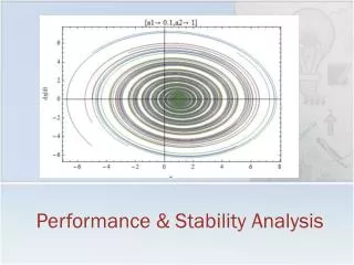
So much for performance… but what about stability and control ? Stability and Control analysis
What it's all about • Our model aircraft needs to be adjusted for performance, but needs also to be stable and controllable. • Stability analysis is a characteristic of "hands-off controls" flight • Control analysis measures the plane's reactions to the pilot's instructions • To some extent,this can be addressed by simulation • An option has been added in XFLR5 v6 for this purpose
Static and Dynamic stability • In the first part, we mentioned static stability • Dynamic stability is about the ability of the object to return to its equilibrium state after a perturbation Statically stable Staticallyunstable Dynamically unstable Dynamically stable Response Response time time
Sailplane stability • A steady "static" state for a plane would be defined as a constant speed, angle of attack, bank angle, heading angle, altitude, etc. • Difficult to imagine • Inevitably, a gust of wind, an input from the pilot will disturb the plane • The purpose of Stability and Control Analysis is to evaluate the dynamic stability and time response of the plane for such a perturbation • In the following slides, we refer only to dynamic stability
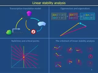
Natural modes • Physically speaking, when submitted to a perturbation, a plane tends to respond on "preferred" flight modes • From the mathematic point of view, these modes are called "Natural modes" and are described by • an eigenvector, which describes the modal shape • an eigenvalue, which describes the mode's frequency and its damping
Natural modes - Mechanical • Example of the tuning fork Shock perturbation preferred response on A note = 440 Hz Amplitude response vibration time T = 1/440 s The sound decays with time The fork is dynamically stable… not really a surprise
Natural modes - Aerodynamic • Example of the phugoid mode The plane returns progressively to its steady level flight = dynamically stable Trajectory response Steady level flight Phugoid period Perturbation by a vertical gust of wind
The 8 aerodynamic modes • A well designed plane will have 4 natural longitudinal modes and 4 natural lateral modes Lateral 1 spiral mode 1 roll damping mode 2 Dutch roll modes Longitudinal 2 symmetric phugoid modes 2 symmetric short period modes
The phugoid … is a macroscopic mode of exchange between the Kinetic and Potential energies Russian Mountains : Exchange is made by the contact force Aerodynamic : Exchange is made by the lift force Slow, lightly damped, stable or unstable
The mechanism of the phugoid Relative wind Constant Cl constant Dive The sailplane accelerates At iso-Cl, The lift increases as the square power of the speed L = ½ S V² Cl The sailplane rises and slows down The lift decreases Response time
The short period mode • Primarily vertical movement and pitch rate in the same phase, usually high frequency, well damped The mode's properties are primarily driven by the stiffness of the negative slope of the curve Cm=f() Response time
Spiral mode • Primarily heading, non-oscillatory, slow, generally unstable The mode is initiated by a rolling or heading disturbance. This creates a positive a.o.a. on the fin, which tends to increase the yawing moment Response Requires pilot input to prevent divergence ! time
Roll damping • Primarily roll, stable Bank angle Due to the rotation about the x-axis, the wing coming down sees an increased a.o.a., thus increasing the lift on that side. The symmetric effect decreases the lift on the other side. This creates a restoring moment opposite to the rotation, which tends to damp the mode time
Dutch roll • The Dutch roll mode is a combination of yaw and roll, phased at 90°, usually lightly damped Plane rotates to starboard Plane banks to starboard Plane banks to port side and reverses yaw direction Plane rotates to port side Top view • Increased lift and drag on starboard side, decreased lift and drag on port side • The lift difference creates a bank moment to port side • The drag difference creates a yawing moment to starboard Rear view
Modal response for a reduced scale plane • During flight, a perturbation such as a control input or a gust of wind will excite all modes in different proportions : • Usually, the response on the short period and the roll damping modes, which are well damped, disappear quickly • The response on the phugoid and Dutch roll modes are visible to the eye • The response on the spiral mode is slow, and low in magnitude compared to other flight factors. It isn't visible to the eye, and is corrected unconsciously by the pilot
Modal behaviour • Some modes are oscillatory in nature… • Phugoid, • Short period • Dutch roll • …and some are not • Roll damping • Spiral Defined by • a "mode shape" or eigenvector • a natural frequency • a damping factor Defined by • a "mode shape" or eigenvector • a damping factor
The eigenvector • In mathematical terms, the eigenvector provides information on the amplitude and phase of the flight variables which describe the mode, • In XFLR5, the eigenvector is essentially analysed visually, in the 3D view • A reasonable assumption is that the longitudinal and lateral dynamics are independent and are described each by four variables
The four longitudinal variables • The longitudinal behaviour is described by • The axial and vertical speed variation about the steady state value Vinf = (U0,0,0) • u = dx/dt - U0 • w = dz/dt • The pitch rate q = d/dt • The pitch angle • Some scaling is required to compare the relative size of velocity increments "u" and "w" to a pitch rate "q" and to an angle "" • The usual convention is to calculate • u' = u/U0, w' = w/U0, q' = q/(2U0/mac), • and to divide all components such that= 1
The four lateral variables • The longitudinal behaviour is described by four variables • The lateral speed variation v = dy/dt about the steady state value Vinf = (U0,0,0) • The roll rate p = d/dt • The yaw rate r = d/dt • The heading angle • For lateral modes, the normalization convention is • v' = u/U0, p' = p/(2U0/span), r' = r/(2U0/span), • and to divide all components such that= 1
Frequencies and damping factor • The damping factor is a non-dimensional coefficient • A critically damped mode, = 1, is non-oscillating, and returns slowly to steady state • Under-damped ( < 1) and over-damped ( > 1) modes return to steady state slower than a critically damped mode • The "natural frequency" is the frequency of the response on that specific mode • The "undamped natural frequency" is a virtual value, if the mode was not damped • For very low damping, i.e. << 1, the natural frequency is close to the undamped natural frequency
The root locus graph • This graphic view provides a visual interpretation of the frequency and damping of a mode with eigenvalue = 1 + iN • The time response of a mode component such as u, w, or q, is • N is the natural circular frequency and Nis the mode's natural frequency • is the undamped natural circular frequency • 1 is the damping constant and is related to the damping ratio by 1 = -1 • The eigenvalue is plotted in the 1N axes, i.e. the root locus graph Imaginary part /2 Real part