Frame Relay
Frame Relay. Accessing the WAN – Chapter 3. Objectives. Describe the fundamental concepts of Frame Relay technology in terms of Enterprise WAN services including Frame Relay operation, Frame Relay implementation requirements, Frame Relay maps, and LMI operation.

Frame Relay
E N D
Presentation Transcript
Frame Relay Accessing the WAN– Chapter 3
Objectives • Describe the fundamental concepts of Frame Relay technology in terms of Enterprise WAN services including Frame Relay operation, Frame Relay implementation requirements, Frame Relay maps, and LMI operation. • Configure a basic Frame Relay PVC including configuring and troubleshooting Frame Relay on a router serial interface and configuring a static Frame Relay map. • Describe advanced concepts of Frame Relay technology in terms of Enterprise WAN services including Frame Relay sub-interfaces, Frame Relay bandwidth and flow control. • Configure an advanced Frame Relay PVC including solving reachability issues, configuring Frame Relay sub-interfaces, verifying and troubleshooting Frame Relay configuration.
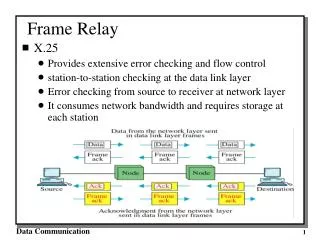
What is Frame Relay? • Frame: Uses Layer 2 encapsulation • Similar to HDLC • Has an address field (and uses it!) • Relay: Fast ‘switching’ at intermediate nodes • Each switch only checks the FCS • No Layer 2 sequencing, acks… (better than old, slow X.25) • Do your error recovery at a higher layer! (L4?)
Logical versus Physical Connections • To physically connect all nodes in a ‘full-mesh’, it takes many connections per site. • Each connection (think T-1 link) costs money!
Introducing Frame Relay • Frame Relay is a packet-switched, connection-oriented, WAN service. • It operates at the data link layer of the OSI reference model. • Frame Relay uses a subset of the high-level data link control (HDLC) protocol called Link Access Procedure for Frame Relay (LAPF). • Frames carry data between user devices called data terminal equipment (DTE), and the data communications equipment (DCE) at the edge of the WAN. • It does not define the way the data is transmitted within the service provider’s Frame Relay cloud. This is ATM in many cases!
Introducing Frame Relay • A Frame Relay network may be privately owned, but it is more commonly provided as a service by a public carrier. • It typically consists of many geographically scattered Frame Relay switches interconnected by trunk lines. • Frame Relay is often used to interconnect LANs. When this is the case, a router on each LAN will be the DTE. • Access Circuit - A serial connection, such as a T1/E1 leased line, will connect the router to a Frame Relay switch of the carrier at the nearest point-of-presence for the carrier. Access circuits
Typical Frame Relay WAN Connections • Each site has a local connection to the ‘Cloud’ • Each connection has a rated bit rate (per PVC)
Frame Relay Standards and Scope • Only used on the ‘edge’ of a cloud (DTE to DCE) • DCE is a switch in the providers network
DTE – Data Terminal Equipment • DTEs generally are considered to be terminating equipment for a specific network and typically are located on the premises of the customer. • The customer may also own this equipment. • Examples of DTE devices are routers and Frame Relay Access Devices (FRADs). • A FRAD is a specialized device designed to provide a connection between a LAN and a Frame Relay WAN.
DCE – Data Communications Equipment NNI UNI • DCEs are carrier-owned internetworking devices. • DCE equipment is provides clocking and switching services in a network. • In most cases, these are packet switches, which are the devices that actually transmit data through the WAN. • The connection between the customer and the service provider is known as the User-to-Network Interface (UNI). • The Network-to-Network Interface (NNI) is used to describe how Frame Relay networks from different providers connect to each other.
Virtual Circuits • A PVC (Permanent Virtual Connection) is setup with a fixed path through the network • Each end is assigned one DLCI (Data Link Conn ID)
Multiple Virtual Circuits on the same Link! • A single Access Line can carry data to multiple destinations • Uses different DLCIs for each destination
Frame Relay Encapsulation • Each L2 frame has an Address (DLCI) and FCS
IETF Frame Relay Frame • Cisco routers support two types of Frame Relay headers. • Cisco, which is a 4-byte header (default, Cisco proprietary). • IETF, which is a 2-byte header that conforms to the IETF standards.
DLCI • A data-link connection identifier (DLCI)identifies the logical VC between the CPE and the Frame Relay switch. • The Frame Relay switch maps the DLCIs between each pair of routers to create a PVC. • DLCIs have local significance, although there some implementations that useglobal DLCIs. • DLCIs 0 to 15 and 1008 to 1023 are reserved for special purposes • Service providers assign DLCIs in the range of 16 to 1007. • Some ‘reserved’ DLCIs include: • DLCI 1019, 1020: Multicasts • DLCI 1023: Cisco LMI • DLCI 0: ANSI LMI
DLCI Connections • Inside the cloud, your Frame Relay provider sets up the DLCI numbers to be used by the routers for establishing PVCs.
LMI – Local Management Interface • LMI is a signaling standard between the DTE and the Frame Relay switch. • LMI is responsible for managing the connection and maintaining the status between devices. • LMI includes: • A keepalive mechanism, which verifies that data is flowing • A multicast mechanism, which provides the network server (router) with its local DLCI. • Themulticast addressing, which can give DLCIs global rather than local significance in Frame Relay networks (not common). • A status mechanism, which provides an ongoing status on the DLCIs known to the switch
LMI Types • In order to deliver the first LMI services to customers as soon as possible, vendors and standards committees worked separately to develop and deploy LMI in early Frame Relay implementations. • The result is that there are three types of LMI, none of which is compatible with the others. • The LMI type must match between the provider DCE switch and the customer DTE device. • The good news is that Cisco routers since 11.2 can automatically sense the LMI type of the DCE
LMI Status Query • DTE can learn what DLCIs are ‘connected’ from DCE
LMI Status Response • The three possible PVC states are: • Active state – Indicates that the connection is active and that routers can exchange data. • Inactive state – Indicates that the local connection to the Frame Relay switch is working, but the remote router connection to the Frame Relay switch is not working. • Deleted state – Indicates that no LMI is being received from the Frame Relay switch,or that there is no service between the CPE router and Frame Relay switch.
DLCI Mapping to Network Address • Manual • Manual: Administrators use a frame relay map statement. • Dynamic • Inverse Address Resolution Protocol (I-ARP) provides a given DLCI and requests next-hop protocol addresses for a specific connection. • The router then updates its mapping table and uses the information in the table to forward packets on the correct route.
Inverse ARP – Know DLCI, Need remote IP • Inverse Address Resolution Protocol (Inverse ARP) was developed to provide a mechanism for dynamic DLCI to Layer 3 address maps. • Inverse ARPworks much the same way Address Resolution Protocol (ARP) works on a LAN. • However, with ARP, the device knows the Layer 3 IP address and needs to know the remote data link MAC address. • With Inverse ARP, the router knows the Layer 2 address which is the DLCI, but needs to know the remote Layer 3 IP address.
Inverse ARP – Step by Step 2 1 3 My DLCI 16 Your IP? My IP is 1.1.1.1 • Once the router learns DLCIs, the router can send an Inverse ARP request to the other end of the PVC. • For each supported and configured protocol on the interface, the router sends an Inverse ARP request for each DLCI. • In effect, the Inverse ARP request asks the remote station for its Layer 3 address. • At the same time, it provides the remote system with the Layer 3 address of the local system. • The return information from the Inverse ARP is then used to build the Frame Relay map. 4 My IP is 1.1.1.2
Configuring Frame Relay Encapsulation Router(config-if)#encapsulation frame-relay {cisco | ietf} • cisco - Default • Use this if connecting to another Cisco router. • ietf - Select this if connecting to a non-Cisco router. • RFC 1490
Configuring Frame Relay LMI Router(config-if)#frame-relay lmi-type {ansi | cisco | q933a} • To manually configure LMI, use the above command. • Cisco routers default to sensing the LMI type. • Don’t get confused with Encapsulation
Minimum Frame Relay Configuration HubCity(config)# interface serial 0 HubCity(config-if)# ip address 172.16.1.2 255.255.255.0 HubCity(config-if)# encapsulation frame-relay Spokane(config)# interface serial 0 Spokane(config-if)# ip address 172.16.1.1 255.255.255.0 Spokane(config-if)# encapsulation frame-relay
Frame-Relay Map • The frame-relay map associates • DLCI to Destination IP address • dynamicrefers to the router learning the IP address via Inverse ARP HubCity# show frame-relay map Serial0 (up): ip 172.16.1.1 dlci 101, dynamic, broadcast, status defined, active
Frame Relay Static Map Note: Static map command disables Inverse ARP!
Verifying Frame Relay interface • The show interfaces serial command displays information regarding the encapsulation and the status of Layer 1 and Layer 2. • It also displays information about the multicast DLCI, the DLCIs used on the Frame Relay-configured serial interface, and the DLCI used for the LMI signaling.
Frame Relay Topologies Most Expensive Most Fault-tolerant Better Cheapest!
NBMA – Non Broadcast Multiple Access Frames between two routers are only seen by those two devices (non broadcast). Similar to a LAN, multiple computers have access to the same network and potentially to each other (multiple access). • An NBMA network is the opposite of a broadcast network. • A nonbroadcast multiple access network is a network to which multiple computers and devices are attached, but data is transmitted directly from one computer to another over a virtual circuit or across a switching fabric. The most common examples of nonbroadcast network media include ATM (Asynchronous Transfer Mode), frame relay, and X.25.
Hub Router • This is known as a Hub and Spoke Topology, where the Hub router relays information between the Spoke routers. • Limits the number of PVCs needed as in a full-mesh topology (coming). A Frame-Relay Configuration Supporting Multiple Sites Spoke Routers
Configuration using Inverse ARP HubCity interface Serial0 ip address 172.16.1.2 255.255.255.0 encapsulation frame-relay Spokane interface Serial0 ip address 172.16.1.1 255.255.255.0 encapsulation frame-relay Spokomo interface Serial0 ip address 172.16.1.3 255.255.255.0 encapsulation frame-relay
Maps using Inverse ARP HubCity# show frame-relay map Serial0 (up): ip 172.16.1.1 dlci 101, dynamic, broadcast, status defined, active Serial0 (up): ip 172.16.1.3 dlci 112, dynamic, broadcast, status defined, active Spokane# show frame-relay map Serial0 (up): ip 172.16.1.2 dlci 102, dynamic, broadcast, status defined, active Spokomo# show frame-relay map Serial0 (up): ip 172.16.1.2 dlci 211, dynamic, broadcast, status defined, active What about Spokane to Spokomo?
Inverse ARP Limitations • Can HubCity ping both Spokane and Spokomo? Yes! • Can Spokane and Spokomo ping HubCity? Yes! • Can Spokane and Spokomo ping each other? No! The Spoke routers’ serial interfaces (Spokane and Spokomo) drop the ICMP packets because there is no DLCI-to-IP address mapping for the destination address. Solutions to the limitations of Inverse ARP • Add an new PVC between Spokane and Spokomo • Warning: May cost you more money from your provider! • Configure Frame-Relay Map Statements • Warning: May have negative side-effects. 3. Configure Point-to-Point Subinterfaces.
HubCity interface Serial0 ip address 172.16.1.2 255.255.255.0 encapsulation frame-relay (Inverse-ARP still works here) Spokane interface Serial0 ip address 172.16.1.1 255.255.255.0 encapsulation frame-relay frame-relay map ip 172.16.1.3 102 frame-relay map ip 172.16.1.2 102 Spokomo interface Serial0 ip address 172.16.1.3 255.255.255.0 encapsulation frame-relay frame-relay map ip 172.16.1.1 211 frame-relay map ip 172.16.1.2 211 Frame-Relay Map Statements Notice that the routers are configured to use either IARP or Frame Relay maps. Using both on the same interface will cause problems.
Mixing Inverse ARP and Frame Relay Map Statements Inverse ARP • The previous configuration works fine and all routers can ping each other. • What if we were to mix IARP and Frame Relay map statements on the same router for the same DLCI? • There would be a problem! Frame Relay maps
Mixing Inverse ARP and Frame Relay Map Statements HubCity interface Serial0 ip address 172.16.1.2 255.255.255.0 encapsulation frame-relay Spokane interface Serial0 ip address 172.16.1.1 255.255.255.0 encapsulation frame-relay frame-relay map ip 172.16.1.3 102 Spokomo interface Serial0 ip address 172.16.1.3 255.255.255.0 encapsulation frame-relay frame-relay map ip 172.16.1.1 211 Added Spokane and Spokomo relying on IARP for mapping DLCI to IP address of Hub City.
Mixed Inverse ARP and Frame Relay Map Statements HubCity#show frame-relay map Serial0 (up): ip172.16.1.1 dlci 101, dynamic, broadcast, status defined, active Serial0 (up): ip172.16.1.3 dlci 112, dynamic, broadcast, status defined, active Spokane#show frame-relay map Serial0 (up): ip172.16.1.2 dlci 102, dynamic, broadcast, status defined, active Serial0 (up): ip172.16.1.3 dlci 102, static, CISCO, status defined, active Spokomo#show frame-relay map Serial0 (up): ip172.16.1.2 dlci 211, dynamic, broadcast, status defined, active Serial0 (up): ip172.16.1.1 dlci 211, static, CISCO, status defined, active
Mixing Inverse ARP and Frame Relay Map Statements Good News: • Everything looks fine! • Now all routers can ping each other! Bad News: • Problem when using Frame-Relay map statements AND Inverse ARP: • This will only work until the router is reloaded, here’s why... Frame-Relay Map Statement Rule: • When a Frame-Relay map statement is configured for a particular protocol (IP, IPX, …) Inverse-ARP will be disabled for that specific protocol, only for the DLCI referenced in the Frame-Relay map statement
Reachability issues with routing updates Frame Relay is an NBMA Network • An NBMA network is a multiaccess network, which means more than two nodes can connect to the network. • Modern Routing protocols depend on broadcast or multicast for updates • In an Ethernet LAN, all nodes see all broadcast and multicast frames. • However, in a nonbroadcast network such as Frame Relay, nodes cannot see broadcasts of other nodes unless they are directly connected by a virtual circuit. • This means that Branch A cannot directly see the broadcasts from Branch B, because they are connected using a hub and spoke topology.
Reachability issues with routing updates Split Horizon prohibits routing updates received on an interface from exiting that same interface. • The Central router must receive the broadcast from Branch A and then send its own broadcast to Branch B. • In this example, there are problems with routing protocols because of the split horizon rule. • Do not forward routing updates learned on an interface back out the same interface • A full mesh topology with virtual circuits between every site would solve this problem, but having additional virtual circuits is more costly and does not scale well.
One Solution: Disable Split Horizon Router(config-if)#no ip split-horizon Router(config-if)#ip split-horizon • To remedy this situation, turn off split horizon for IP. • Of course, with split horizon disabled, the protection it affords against routing loops is lost. • Split horizon is only an issue with distance vector routing protocols like RIP, IGRP and EIGRP. • It has no effect on link state routing protocols like OSPF and IS-IS.
Another Solution: subinterfaces • To enable the forwarding of broadcast routing updates in a Frame Relay network, configure the router with subinterfaces. • Subinterfaces are logical subdivisions of a physical interface. • In split-horizon routing environments, routing updates received on one subinterface can be sent out on another subinterface. • With subinterface configuration, each PVC can be configured as a point-to-point connection. • This allows each subinterface to act similar to a leased line. • This is because each point-to-point subinterface is treated as a separate physical interface.
A key reason for using subinterfaces is to allow distance vector routing protocols to perform properly in an environment in which split horizon is activated. • There are two types of Frame Relay subinterfaces. • Point-to-point: One IP, one DLCI • Multipoint: One IP, multiple DLCIs Mulitpoint Point-to-point
Configuring Frame Relay subinterfaces RTA(config)#interface s0/0 RTA(config-if)#encapsulation frame-relay ietf Router(config-if)#interface serial number subinterface-number {multipoint | point-to-point} Router(config-subif)# frame-relay interface-dlci dlci-number • Subinterface can be configured after the physical interface has been configured for Frame Relay encapsulation • Subinterface numbers can be specified in interface configuration mode or global configuration mode. • Subinterface number can be between 1 and 4294967295. • At this point in the subinterface configuration, either configure a static Frame Relay map or use the frame-relay interface-dlci command. • The frame-relay interface-dlci command associates the selected subinterface with a DLCI.
Configuring Frame Relay subinterfaces RTA(config)#interface s0/0 RTA(config-if)#encapsulation frame-relay ietf • The frame-relay interface-dlci command: • Required for all point-to-point subinterfaces. • Required for multipoint subinterfaces for which inverse ARP is enabled. • Cannotbe used on physical interfaces.
Multipoint versus Point-to-Point multipointsubinterfaces : • Multiple DLCIs • Use frame-relay map • Use interface dlci statements • Use Inverse-ARP point-to-point subinterfaces : • One DLCI • Use interface dlci statements • NO frame-relay map statements • NO Inverse-ARP Mulitpoint Point-to-point
Notes • Highly scalable solution • Disable Split Horizon on Hub router when running a distance vector routing protocol • Interface Serial0 (for all routers) • encapsulation frame-relay • no ip address • HubCity • interface Serial0.1 mulitpoint • ip address 172.16.3.3 255.255.255.0 • frame-relay interface-dlci 301 • frame-relay interface-dlci 302 • no ip split-horizon • Spokane • interface Serial0.1 point-to-point • ip address 172.16.3.1 255.255.255.0 • frame-relay interface-dlci 103 • Spokomo • interface Serial0.1 point-to-point • ip address 172.16.3.2 255.255.255.0 • frame-relay interface-dlci 203 Multipoint subinterface at the Hub and Point-to-Point Subinterfaces at the Spokes One subnet