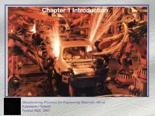
Advancements in Automotive Engineering Materials and Production Methods
Explore the utilization of advanced materials and production techniques in automotive engineering. Learn about the Duratec V-6 engine components, manufacturing processes, and the importance of materials like aluminum. Discover the various methods used to create automotive parts, from casting to machining. Dive into the world of flexible manufacturing systems and their impact on the industry.

Advancements in Automotive Engineering Materials and Production Methods
E N D
Presentation Transcript
Duratec Engine FIGURE 1.1 Section of an automotive engine - the Duratec V-6 - showing various components and the materials used in making them. Source: Courtesy Ford Motor Company. Illustration by David Kimball.
Shapes and Production Method TABLE 1.2 Shapes and Some Common Methods of Production
Engineering Materials FIGURE 1.4 An outline of engineering materials
Aluminum Automobile FIGURE 1.5 . (a) The Audi A8 automobile, an example of advanced materials construction; (b) The aluminum body structure, showing various components made by extrusion, sheet forming, and casting processes. Source: Courtesy of ALCOA, Inc.
Production Methods for a Simple Part FIGURE 1.6 Various methods of making a simple part: (a) casting or powder metallurgy, (b) forging or upsetting, (c) extrusion, (d) machining, (e) joining two pieces.
Machining of a Mold Cavity FIGURE 1.8 Machining a mold cavity for making sunglasses. (a) Computer model of the sunglasses as designed and viewed on the monitor. (b) Machining the die cavity using a computer numerical control milling machine. (c) Final product produced from the mold. Source: Courtesy Mastercam / CNC Software, Inc.
Flexible Manufacturing System FIGURE 1.9 General view of a flexible manufacturing system, showing several machines (machining centers) and an automated guided vehicle (AGV) moving along the aisle. Souce: Courtesy of Cincinnati Milacron, Inc.